How to make a satellite converter with your own hands. Do-it-yourself installation and configuration of a satellite dish. Receiver and equipment
Among ordinary, untrained users, there is an opinion that it is almost impossible to install and configure a satellite system on your own. In fact, this is not true at all. Below - simple instruction for "dummies", about how to independently install and configure a satellite dish without calculations, satellite finders and other attributes of professionals. If you are a professional installer, then the following material is unlikely to be of interest to you.
Although any information can now be found on the Web, I still tried to collect all the basic information I received on one page - for convenience. I’ll just try to tell in my own words and with pictures how I installed and configured the satellite system. I must say right away that the installation of ONLY an offset fixed antenna is being considered, and not a direct-focus or motorized one. And yet - it is possible that no matter how you try, you may not be able to install and configure the antenna yourself. Then you have to invite a professional installer. It's hard for me to imagine how this can be, but in the forums there were people struggling for a couple of days in futile attempts to tune the antenna. In other cases, an independent choice of components and self-installation can save some, sometimes considerable, amount. Among other things, I personally was just interested in installing everything myself. What is the difference between installing and configuring the system "by eye" from a professional installation? Almost nothing. With the exception of a more accurate initial calculation (which saves a lot of time), the mounting system and the principle of tuning the antenna are the same.
Warning: all work related to heights and electricity is life threatening!!! If at least something causes the slightest concern, do not take risks, trust the professionals!!! You make an independent installation at your own peril and risk !!! In any case, remember about safety precautions and that all dangerous high-altitude work is performed only by professionals with proven safety devices !!!
List of basic concepts
TV satellite- a spacecraft located in the geostationary orbit of the Earth and sending a television signal to a certain territory of the Earth through a transponder. All satellites are in the plane of the equator, therefore they are at the same latitude, but differ in longitude. In addition to the name, they also have the designation of longitude. For example, Amos 4W means the satellite is called Amos and is at 4 degrees West (W is West). Hotbird 13E is a satellite of Hotbird, located at 13 degrees East (E is East). Based on the fact that the satellites are "fixed" at certain points in the orbit, they also have certain areas of coverage of the Earth's territory.
Transponder- a transceiver located on the satellite. It is characterized by the width and direction of the beam being sent and the frequency of broadcasting. Broadcasting is carried out in two main ranges - C-Band and Ku-Band. In the C band (4 GHz), mainly American and Russian satellites broadcast, in the Ku band (10.700-12.750 GHz) - European ones. Broadcasting is carried out in linear or circular polarizations. Which, in turn, differ in vertical (V) and horizontal (H) for linear polarization and left (L) and right (R) for circular polarization. When they say “signal from transponder 11766H”, they mean a transponder broadcasting at a frequency of 11766 MHz with a horizontal
polarization. There are from several to dozens of transponders on the satellite
things.
Satellite antenna- the main element of the subscriber's satellite system for receiving a signal from the satellite. If you say in simple terms- the antenna "collects" a weak reflected satellite signal over its entire surface and focuses it to a certain point, where the converter is installed. The most common antennas are direct focus and offset. Direct-focus mirrors are a parabolic mirror with a focus in the geometric center, while offset ones have a shifted focus (below the geometric center of the antenna). Accordingly, the converter for a direct-focus antenna is installed in the center, for
offset-shifted to the bottom. Offset antennas are the most widely used among ordinary users. They are cheap, easy to install and set up. Antennas are produced various diameters and from various materials. The material is usually Aluminium alloy or steel. There are fixed antennas (rigidly fixed) and antennas with an actuator (motor suspension). Motorized suspension rotates the antenna at specified angles and allows you to receive a signal from a huge number of satellites that are in the field of view. Setting up the latter for a beginner is not very easy. The size of the antenna is selected individually, depending on the signal strength required to view the satellite. The diameter of the antenna must be selected with some margin, since atmospheric precipitation (heavy rain, snow) creates significant interference with the satellite signal. This is especially true for the Ku-band. But at the same time, there is no need to go to extremes - if an antenna with a diameter of 0.9 m is enough, absolutely
it is not necessary to buy a 1.5m antenna - it weighs more and its area
more exposed to the wind.
Converter- a device designed to receive a satellite signal reflected from an antenna and installed on an appropriate holder at the focus of the antenna. The main purpose of the converter is to convert the frequency of the received satellite signal (for example, for the Ku-band it is from 10.7 to 12.75 GHz) to an intermediate one (900 - 2150 MHz), at which the attenuation of the signal transmitted in the cable will be less. Since the power of the received satellite signal is very small, the second important task of the converter is to amplify it to an acceptable level for the receiving path of the receiver. Since any converter introduces its own noise level into the signal, but is also low-noise, it is also called LNB (Low Noise Block). Converters are designed to operate in linear polarization or circular and are selected depending on which of the polarizations the satellite is broadcasting in (for example, popular NTV + packages are broadcast in circular polarization and the universal linear polarization converter, despite the name “universal”, is not suitable for reception). If the converter is universal, it switches to the specified polarization with a voltage of 13/18 V supplied by the receiver. 13 V - vertical polarization, 18 V - horizontal. One more nuance: converters come with 1st output, 2nd, 4th, 8th. Based on how many independent viewpoints will be installed, a converter with the appropriate number of outputs must be installed, since all converter outputs are independent.
Multifeed– holder for additional converter. Since the satellites are located in geostationary orbit relatively close to each other (according to
to certain standards), it is possible to simultaneously receive a signal on one antenna using a multi-feed from several nearby satellites. A classic example is 3 satellites (Hotbird 13E, Sisius 4.8E, Amos 4W) received on 1 fixed antenna. As a rule, a converter is installed on the main (focal) antenna holder, tuned to Sisius 4.8E, on the 1st multifeed - converter on Hotbird 13E, on the 2nd multifeed - converter on Amos 4W.
Disek (DiseqC)- This is a device that switches the signal from several converters to 1 cable. Since the receiver can only receive a signal from one satellite at a time, the converter corresponding to this satellite must be connected to the receiver. This is exactly what the disk does - it connects to the receiver
necessary in this moment converter. Diseks are different, designed to work according to a specific protocol. The DiseqC 1.0 protocol is unidirectional and is used when the number of converters is not more than 4. DiseqC 2.0 is the same, only bidirectional and compatible with 1.0. DiseqC 1.1 is used to connect more converters. Protocol 1.2 is used to control the positioner.
A coaxial cable is connected to the inputs and output of the disc via F-connectors.
I think you should not talk about connectors and cable, everything is clear here. However, the cable must necessarily have a wave impedance of 75 ohms, made of high-quality materials that can withstand severe temperature changes and have a good shielding braid. The core material is steel, copper, copper-plated steel - it’s unambiguous to say that it’s unlikely to work better.
Antenna bracket- a simple metal holder that is attached to the wall (as a rule) and to which the antenna is attached. It must be made as securely as possible so that the wind does not rip off the antenna.
Satellite receiver- a device that receives a satellite signal from a converter and displays it on a TV in the form of a familiar picture with sound; Smile Choosing a receiver is the most difficult task when choosing a satellite system.
There are receivers for both open non-encrypted channels (FTA) and encrypted ones, with card readers, with slots for additional decoding modules, with an emulator, with various video outputs, with a hard drive and other useful and not very functions. Here, as they say, for any preference and any wallet. There is one important point: today, satellite broadcasting in HD format (high-definition video) and MPEG4 is being actively put into operation. Receivers that support these formats are usually much more expensive than usual. Therefore, before buying a satellite system, you need to decide what content you will watch and what kind of receiver you need for this. Cheap receivers are usually no different high quality picture and sound, great functionality and fast channel switching. Although there are exceptions. Separate nuance-emulator in the receiver. As can be seen from its name, the emulator is intended for software emulation of the operation of a smart card. What is it for? A huge number of channels from different satellites are protected by encodings. Encodings are different - Viaccess, Seca, Irdeto, Nagravision, Biss, etc. For example, some package of channels is being broadcast in Biss encoding and you want to watch it (the antenna is tuned to
desired satellite), but you do not have a smart card. Then look for a software emulator in your receiver (usually it is written in undocumented features) and turn it on. Enter the channel access keys - and if everything is in order - watch it. As a rule, emulators in modern receivers support several encodings. Another application of the emulator is a phenomenon popularly referred to as "sharing" or "card-sharing". Yes, and yet, when choosing a receiver, you should pay attention to the availability and regularity of the outgoing software. In other words, firmware. In new firmware, as a rule, errors that occur are removed, parameters of satellites, transponders, new codes for the emulator, etc. are added.
Choice of accessories
To begin with, for some time I studied the Internet to get acquainted with the issue (since I was a complete teapot and had a very illusory concept of what a disc or transponder was, but I wanted to watch satellite TV). I decided what content and from which satellites I want to watch (at the end of this article you can look at the lists of the most popular channels in our places and some links), what is accepted in my region and on what diameter of the antenna, and also got acquainted with the advice of experienced , among which Vladbel helped me a lot, for which special thanks to him Smile As a result, for
For viewing, the satellites Amos 4W, Sirius 4.8E, Hotbird 13E per antenna 0.95m and Eutelsat W4 36E at 0.85m were selected. I chose http://www.agsat.com.ua/ as a Kiev store - everything is in one place and, among other things, they are one of the sellers of the original equipment of the same brand recommended by the Openbox manufacturer, and my soul lay precisely in Openbox Smile By the way, both receivers I bought in Agsat and receivers bought there for my friends were ALREADY flashed with lists of satellites and lists
favorite channels from popular satellites 4W + 5E (4.8E) + 13E, and this concerned not only Openboxes. Convenient for those who do not want to bother too much with stuffing favorites.
What was purchased and what were the selection criteria:
- Offset antenna 0.95m made in Kharkiv. Painted steel. For signal reception from Amos 4W, Sirius 4.8E, Hotbird 13E.
- Offset antenna 0.85m made in Kharkiv. Painted steel. To receive a signal from Eutelsat W4 36E.
- Receiver Openbox X-810. Firstly, Openbox has the most powerful technical
support (new firmware is released almost every couple of weeks),
secondly, excellent picture quality, thirdly, a built-in emulator,
fourthly, support for LanComBox (for fans of "sharing" Smile. - Three universal converters of linear polarization SINGLE TITANIUM TSX 0,2dB. Declared low noise level.
- One converter of circular polarization SINGLE Circular INVERTO IDLP-40SCIRCL for Eutelsat W4 36E (NTV+).
- Two multifeeds.
- Two brackets for antennas.
- Disk-switch of a signal from 4 converters in 1 cable connected to a receiver.
- Coaxial antenna cable, impedance 75 Ohm, coil 100m.
- 10 antenna screw-on F-connectors.
- 6 anchor bolts "under the nut" 8x72, washers, nuts and grover washers.
- Plastic self-tightening ties.
- Steel cable with clamps for fixing the antenna cable on it and lowering it from the roof.
- Plastic box for disk.
- Lancombox is a device for sharing (whoever wants, can search any search engine for the concept of "card-sharing" Smile.
The budget for all this stuff was 1346 hryvnias or ~$270.
Installation
The antenna must be installed in the line of sight of the south direction. Direct means that there should not be any obstacles in the form of houses, trees and other things in front of the antenna. It is for this reason that the most optimal places for installing antennas are balconies and roofs. Since my windows are on the first floor and are not directed far to the south, it was decided to install antennas on the roof. Fortunately, the roof of my typical 9-storey panel house is flat, which made installation easier (if there is no free access to the antenna with a converter number greater than 1 after installing it on the bracket, see below *). What I needed on the roof besides antennas with their mounts:
- Perforator with drill bits with pobedite tips. The drill diameter is chosen slightly smaller than the diameter of the anchor bolt. Much less - it is impossible - the anchor will not enter the wall. More - it will “hang out” and it really won’t be possible to tighten it.
- Phillips screwdriver.
- Ring wrench for 10.
- Ring wrench for 13.
- Wrench.
- Hammer.
- Knife for cutting papers (for stripping the cable under the connectors).
- Wire cutters.
- Receiver with remote control.
- Small TV.
- 220V with extension cord for 3 outlets.
The most interesting questions are where to direct the antennas? How to determine the direction? How to set up antennas without a satellite finder (a device for setting up satellite dishes costs from $400)? Since in my case it was decided to make the adjustment "by eye", I decided to determine the direction logically simply - I just looked where the antennas on the neighboring roof were directed and
decided to turn mine in the same direction /
Antenna with 3 converters - definitely Sirius, Hotbird, Amos - we have a lot of these and installers mainly install them. Looking at the neighboring houses, you can find many of these and they are all directed in the same direction. That is why I had no doubts. To the left of it with one converter - probably NTVshnaya - we also have enough of those. If you do not have such guidelines, then things are worse. You need to determine the south direction and try to direct the antenna there. Once again, an indispensable condition is that in no case should there be any visible obstacles in the direction of the satellite in front of the antenna !!! Among other things, in a situation where the antenna is installed under someone's balconies or visors, make sure that
streams of water or snow from the upper visor did not fall directly on your antenna. It does not bode well for the reception.
I decided to mount my antennas to this elevator shaft:
Nondescript, of course, on the roof, but this is not a renovation in the apartment Smile Defined
installation site, marked the holes for the brackets, drilled them with a perforator, hammered the anchors inside and fixed the brackets (I did not fully photograph the next steps, so almost all the photos will be from already installed systems). I won’t dwell on fixing the brackets, I think that everything is clear with this, the work is mechanical. Still, if someone does not know what an anchor bolt is, I'll show you how it looks:
It consists of a glass and a bolt inside it. The bolt has a thread for a nut on one side and a thickened cone on the other. Exactly as in the figure, from left to right, carefully, so as not to damage the thread under the nut, it is driven into the drilled hole.
At the same time, I recommend loosening the nut, but not completely unscrewing it, otherwise the bolt runs the risk of completely falling into the hole, then you won’t get it. The same applies to putting the bracket on the bolts (the nuts will still have to be removed) - make sure that the bolts do not fall inside the glass, I recommend pulling them as much as possible before putting the bracket on or pulling the nut a little so that the cone enters the glass a little and the bolts do not stagger . The glass should be flush with the wall, and the thread with the nut, respectively, should be outside the hole.
The principle of operation of the anchor bolt is as follows: when the nut begins to be tightened with a wrench, it pulls the bolt inside the glass outward due to the thread. The cone located at the end of the bolt enters the glass and expands it as much as possible inside the hole. As a result, tearing such a bolt out of the wall is a far from trivial task. That is why it is recommended to hang the bracket on self-wedging anchor bolts, and not on screws with plastic dowels.
However, the choice of attachment is a personal matter for everyone. The only thing - if you still choose anchors - look at their quality, in particular at the material and thickness of the glass. Because the anchors are too flimsy and will hold accordingly.
When installing on a balcony, you can generally drill a wall and pass through it threaded rods of the appropriate length (such are sold in stores). Fastened with nuts on both sides.
Back to installation.
The first antenna was tuned with 3 converters for Sirius, Hotbird, Amos, the second for Eutelsat 36E. At first, the brackets were screwed onto screw anchor bolts, later I changed them to wrenches. Screws proved to be unreliable. The photo shows the first unsuccessful attempts in the form of the remaining holes. By that time, the brackets were also repainted to enhance the original painting:
In the photo above, the antenna is already assembled, with converters, cable, etc. Initially, the antenna was simply assembled, hung on the bracket, and the converters with the cable clung later. A thin metal cable - I just had an extra one and I threaded it through the antenna mount and screwed it to the elevator shaft post in case the wind rips out the anchors so that the antenna does not dive off the roof Smile Actually, this is almost impossible, but let it be - so I thought. To adjust the antenna in the vertical and horizontal planes, it is required to clamp the mount so that the antenna does not independently change its inclination, but at the same time it can be moved in planes with some effort. These nuts until the final adjustment are not much
are tightened:
The left screw that is not clamped allows you to adjust the antenna in a vertical plane, 2
not clamped right - rotate the antenna relative to the bracket in a horizontal plane.
Next, both multifeeds are put on the central holder of the antenna converter, converters are inserted into all holders, and everything is tightened so that the converters in the multifeeds can be turned with some effort in all
planes (cables are connected to the converters later). The photo below shows what multifeeds are and how they are attached:
After that, the setup process begins. A piece of cable a couple of meters long is screwed to the central converter with an F-connector, the other end of the cable is screwed to the receiver. From some site I have pictures of what an F-connector is and how to properly wind it onto a cable.
The receiver is connected to the TV, only after that the 220V power is turned on. An important point - when winding the F-connector onto the cable, you must carefully monitor that the thin conductors of the shielding braid of the cable do not close with the central core, otherwise the receiver can be damaged !!!
I turn on the TV, receiver, go to the menu Installation-Search for channels. In the list of satellites on the left, I select Sirius 2 / Ku 4.8E - it is on this satellite that the rigidly fixed central converter will be configured. From the menu on the right, choose:
- LNBP: On(turn on converter power)
- LNBP Type: Universal(universal converter type, according to the ones I bought)
- LNBP Freq: 10600/9750(indicated on converters)
- 22Khz: Auto(I leave the signal to switch the disc)
- DISEqC: None(I leave it like that, since the signal is connected directly for now, and not through a disk)
Next, with the yellow button on the remote control, I go to the Transponder submenu and select the transponder on which I will look for a signal (I advise you to pre-order several transponders selected from satellites with different polarizations and REALLY WORKING free-to-air channels (FTA). The list can be found at the links below.
For example, in my case, for starters, it will be a 11766H transponder broadcasting at a frequency of 11766 MHz with horizontal polarization. For convenience, the signal quality can be displayed on Full Screen the Info button. I will focus on the lower scale "Quality":
What do we see in this photo? A bleak picture, signal quality - 0%! In fact, what should you expect? After all, the antenna is still “looking” towards the satellite very approximately.
Then comes the most difficult moment, which requires considerable endurance - this is tuning the antenna in planes. Why shutter speed is needed - literally a few millimeters, and there will be no signal. Not that it will be bad, but it will not be at all! The setup is as follows - you need to install the antenna in a certain vertical position, in my position it was approximately like this:
After that, you need to very, very smoothly rotate the antenna in a horizontal direction and at the same time carefully look at the quality scale, first in one direction, and if the scale does not change from 0, then in the other. When it turns out that the quality scale has grown to at least 10-15, this is already the first success, you can stop and take a break. If it is not possible to find a signal in the entire horizontal plane, you need to slightly change the vertical angle of the antenna and start moving again in the horizontal plane until the signal appears. When at least some signal is found: now you need to try to move the antenna even more smoothly left and right and achieve the maximum level of signal quality. Having achieved this, you need to try to achieve an even greater signal by moving the antenna very smoothly up and down. After that, you can try
slightly rotate the converter around its axis in the holder (there are marks on the converter for this):
The maximum signal can be achieved ONLY by the combination of all these adjustments. Another nuance - if you can’t find a signal under any circumstances, and you double-checked everything 100 times, including the receiver settings, it makes sense to try another converter, maybe this one is faulty. I get the maximum signal level that I can pull out:
It would seem that you can calm down and tighten all the adjusting screws? No matter how
So! After all, the setting was made for a transponder broadcasting in horizontal polarization (there is a letter H in the picture at the end of the 2nd period), but you also need to configure some kind of transponder in vertical (V) polarization:
In my case, turning the converter in the holder counterclockwise helped to achieve best quality signal in vertical polarization.
After that, you can scan the transponders (look in the documentation with your
receiver how to do it) and visually see if the channels are received and if they correspond to the selected satellite:
When signals in horizontal and vertical polarizations are at their maximum
that can be pulled out, it is necessary to tightly tighten all adjusting nuts under tightened. And here there is one unpleasant moment - you tighten the nut, while the antenna slightly changes its direction, and the signal quality can noticeably go away! So you also need to tighten it very carefully. Everything, the antenna and the first converter are configured. I turn off the receiver from the outlet, wind the cable from the central converter onto the converter on the left (to the one on the multifeed, if you look at the antenna
front), turn on everything, select Hotbird 13E in the menu, the same menu settings on the right as for Sirius, select a working transponder and try to set the maximum signal quality. Only this time I am adjusting not the antenna, but the converter itself on the multifeed. It can move in all planes with respect to the focus of the antenna - left, right, up, down, forward, backward:
All nuts are tightened when the signal is maximum. Don't forget to check in
both polarizations. Scanning Hotbird transponders and checking for any free channels visually.
I turn everything off again, twist the cable to the 3rd converter, turn everything on, select Amos 4w and make settings for it. Everything is similar. After that, the tuning of the first antenna can be considered completed.
Second antenna. Which I am going to set up on Eutelsat W4 36E (NTV+). It's easier - one converter. Moreover, since it is of circular polarization, it is not very important how it will be deployed inside the holder. Best of all, with the cable down so that precipitation does not accumulate on it:
Accordingly, you need to adjust the antenna in the horizontal and vertical planes. I turn everything off, twist the cable to this converter. The settings according to the purchased converter are as follows:
I set up the second antenna, check the antenna in both polarizations on different
transponders. Since the converter is designed for circular polarization, they are checked not for H and V, but for L and R (left and right).
That's all. You can turn everything off. Now you need to make signal switching through disk.

My disk has 1 receiver output, labeled REC, and 4 inputs for
converters, referred to as 1,2,3,4. I connect the converters like this:
- Sirius
- hot bird
- Eutelsat
With the connection, everything is simple - a segment is connected to each converter
cable connected to the corresponding disk input. If you install one antenna with the 1st converter, then the disc is not needed. If one antenna for 2 converters and 2 ports are free on the disk, it's okay. Disek is installed near the antennas and preferably is enclosed in a waterproof box (I bought it in an electrical store) so that precipitation does not fall on it:
Holes for ventilation are desirable in the bottom of the disek box. Acute
cable bend angles are not allowed! F-connectors on the converters are closed either with the caps supplied with the kit or with heat shrink tubing:
By the way, in the above photo you can see the distances between the converters and their angles of inclination. On the right is the antenna pointing at the Eutelsat W4.
I configure the disk protocol in the receiver menu (in my case 1.0) and the distribution of converters according to the inputs (ports) of the disk:
The pictures show which inputs (ports) of the drive are assigned converters (to which satellite). 0/12V: On only for LanComBox. If you do not have it, then you do not need to turn on 12V. I save the changes, check if all the disk inputs are working (ie, are there a signal on all the configured satellites).
Someone may have a question: “why not immediately connect all the converters to the disk, register all the inputs and tune the antennas?” The answer is simple - with a really idle disk, you will kill a LOT of time and nerves trying to build a signal that cannot be found by definition. Among other things, without a disc, you will quickly determine whether you bought a working converter.
I tighten the cables with ties so that nothing dangles. Stays tight
attach the cable to the cable, pull the cable down and tighten. Install a cable in the apartment, connect the receiver, TV and watch satellite TV Smile
Here's what I ended up with on the roof:
*- If there is no access to the antenna after installing it on the bracket:
when there is only one converter on the antenna, everything is clear here, nothing complicated, it is fixed
rigidly on the antenna, the antenna is hung out of the window (or somewhere else) on the bracket, and adjusted in the vertical and horizontal planes all from the same window (return to the warning at the beginning of the instructions !!!). What to do if you need to set up 1 additional converter (or more) on the multifeed? At the dacha, I did this: I screwed the bracket to an old tall pedestal, put the assembled antenna on it, put the whole structure in front of a wide-open window and set it up like that. By the way, a curious moment - with the first inclusion, with approximate antenna tilts, without additional settings, I got a quality level on Sirius of more than 70%! I didn't believe my eyes. In a word, in this form, I set up all 3 converters, carefully clamped everything, hung the bracket over the window and hung the antenna on it with the already tuned converters. It remains only to adjust it in planes.
An important point in the high-altitude installation of satellite dishes: in addition to safety precautions and self-insurance in the first place, when hanging the antenna on a bracket or mast, always protect the antenna as well. Just imagine
imagine what a passer-by’s head or an expensive BMW’s body can do with an antenna planned from a height.
Something else - many people advise grounding antennas installed on the roof,
however, some installers are vehemently opposed to this. I am inclined to conclude that grounding the antenna still does not hurt.
Step into space from the steps of the university
Astronautics can be different - private, student, amateur. All these are different facets of the same phenomenon, namely, the ability to penetrate into orbit not only for state corporations of the largest space powers, but also for an almost ordinary person. Yes, the launch vehicle industry, space stations and space tourism will require trillions of dollars of investments for a long time to come and remain the lot of the elite, but touching space at a certain level is now available to anyone!
Photo from personal archive.
My interlocutor is Alexander Shaenko, an engineer who has been working in the space industry for more than ten years, a candidate of technical sciences, a lecturer at Moscow State Technical University. Bauman. He took part in the development of Angara launch vehicles, the Boeing Dreamliner aircraft, and worked as a lead engineer at one of the first private Russian space companies. Today, Shaenko, together with the students he teaches, is creating a satellite almost in garage conditions and preparing it for launch:
“We want to launch a satellite with the help of students, which has never been done before,” Alexander begins.
- How? It is known that quite a few satellites have already been launched by students - both at Moscow State University, and at the Moscow Aviation Institute, and at your place in Baumanka, and at the Siberian State Aerospace University ...
- In fact, almost all of these student satellites are very, very conditional. They are launched according to the university’s scientific work plan, which is mainly prepared by university professors and researchers, and are mostly manufactured at state-owned enterprises in the space industry - that is, students there, in fact, just stand nearby and observe.
— And what do you plan to change in the current approach to student astronautics?
“I once worked for a young private aerospace company, and to demonstrate the seriousness of our plans, we made a satellite. Literally - they came to the office, where there were only tables and chairs, and a year and a half later, our satellite went into orbit! It was equipped with equipment for monitoring radio broadcasts and collecting data on ships. This satellite, although not scientific, was built by the hands of recent students, and not ordered from aerospace state corporations, and quickly! I believe that within the framework of university cosmonautics there should be not only serious satellites with a scientific program, in which students are involved insofar as, but also simpler satellites, even if without the goal of obtaining new scientific data, but designed, calculated and made directly by the hands of students.
What kind of satellite are you going to launch?
“This is a visual observation satellite called Mayak, which we started working on last summer. The whole task of the satellite is to be visible from the Earth, but very clearly! Anyone can see it with the naked eye, and you won’t be able to confuse it with anything - the glow will be so bright! After being put into orbit, a gas reactor will start working on the satellite and inflate the polymer metallized shell in the form of a huge pyramid with gas. Its facets will reflect the sun's rays and glow brighter than the most visible stars.
- At what stage is the work today?
— We test the equipment — an inflatable shell, a gas reactor, electronics. The work is close to completion - we recently tested the inflation of the shell and the operation of the gas reactor in the stratosphere, at an altitude of 10 kilometers - in extremely low (down to minus 70 degrees) temperatures. To do this, the nodes of the satellite were raised on a balloon filled with helium. This summer, the final "run" is planned - raising the entire satellite assembly to a height of about 40 kilometers, practically into near space - there is already very rarefied air. This lift is also feasible on a helium balloon.
- A balloon capable of lifting 4 kg must be rather big ... Are such experiments safe for aviation?
- Not even 4, but 6 kilograms - in addition to the satellite, the equipment for monitoring its parameters will take off on the ball. The ball is really huge - on the ground it has a diameter of 4 meters, and at a height due to the difference in pressure, it will swell up to 20 meters in diameter! Such launches are really dangerous for aviation, but there is one enthusiast in our team who is the only one in Russia who is officially involved in lifting balloons into the stratosphere - he has permission from the military, aviation services, etc. Each launch requires separate approval and is strictly supervised. This person has sufficient experience in lifting high-altitude balloons.
— How is the project financed?
- We used crowdfunding - the collection of voluntary donations on an Internet platform where techies and IT people gather. We managed to collect about 250 thousand rubles, for which we purchase materials for the construction of the satellite. Everything is extremely open with us and the “Tom Sawyer principle” is used - remember how he accepted money and toys from his friends in exchange for permission to paint the fence a little? I mean, donating allows anyone to join the student team.
- After the manufacture of the satellite, the task will be to put it into orbit, which you can no longer carry out on your own. How do you plan to do it and how much does it cost?
- Today, many companies in the world offer "transport services" - they put any satellites into orbit, including private ones. A satellite made in Russia will easily launch an American rocket and vice versa - no adaptation to the rocket is required. Now about the prices. The launch of a small satellite is quite affordable - delivering 1 kilogram of payload into orbit will cost about 2 million rubles. Our satellite weighs 4 kilograms - that is, its launch costs 7-8 million rubles.
— Where should this considerable money for students come from?
- This, of course, is the most painful issue of any student or amateur project. We are looking for sponsors… There is a prospect.
- A couple of years ago, leading scientific and technical universities signed an agreement with Roskosmos on the creation of a certain “Space Scientific and Educational Consortium”. Do the opportunities for a free launch without reference to the scientific value of the satellite still exist?
“Honestly, I don’t know anything about the activities of that consortium. But on the other hand, there are cases when universities were told: yes, we will launch your satellite for free, but you must prove that it is safe for the rocket itself and for other satellites that it puts into orbit. To do this, you need to go through a series of examinations ... for several tens of millions of rubles! One way or another, today Roscosmos is controlled by another person. Today we are cooperating with the new head of Roscosmos and the United Rocket and Space Corporation and we hope for his help in our project. "Space of small forms" today is on the rise all over the world, it needs to be popularized and promoted, and made easier by affordable projects that everyone can take part in, and not just "adult scientists"!
Satellite dishes have somewhat lost their significance for society in recent years. The reason is the appearance on sale of digital TV set-top boxes. Nevertheless, this equipment remains in demand, especially if the population lives outside the urban area.
Buying equipment is not a problem, but installation satellite dish It may well become a serious task with an independent approach to installation. However, the task can be greatly facilitated if you have basic knowledge. We will talk about how the installation is carried out using the example of the popular Tricolor system.
Even when dealing with a traditional television antenna, and in such cases, installation requires at least minimal knowledge and skills. Satellite equipment is much more complex than conventional TV reception.
If conventional equipment has two main concepts - a cable and a plug, a system where reception from a satellite is carried out has a number of technical concepts:
- Satellite antenna.
- Converter.
- Multifeed holder.
- Bracket.
- Receiver.
Let us consider in more detail each of the constituent elements of satellite equipment.
– signal source to be received by the antenna. Accordingly, in order to receive a constant signal, a constant direction of the antenna to the satellite is necessary.
An apparatus in geostationary Earth orbit is, in fact, a standard space satellite, but the main functionality of such an apparatus is the broadcast of a television signal
There are different satellites and different antenna designs, but the principle of tuning is almost the same for all.
For this television reception technology, a satellite dish is used, which is a “dish” disk of different diameters, equipped with a conversion device - converter.

Part of the equipment is an antenna that provides reliable reception of the TV receiver signal from the satellite. Given the frequency of the transmitted signal, the antenna looks somewhat different than traditional reception designs.
This is a module of small geometric dimensions, usually cylindrical, attached directly to the "front" part of the satellite dish.
The disk antenna has a special design that allows you not only to receive a television signal, but to additionally concentrate and direct it to one point - namely to the converter. It, in fact, is the primary signal amplifier, from which the signal is fed through the cable to the receiver.

One of the components of a satellite dish that needs special attention during installation, ensuring a high degree of tightness of the structure
A special rod holder is used to fix the module. The device called "multi-feed-holder"- this is the same rod-holder, only slightly modified. Allows you to place several converters to work with different satellites.
The bracket is, in fact, a mechanical structure that is assembled from component parts and fixed at the intended installation site of the satellite dish. As a rule, such a place is the wall of the building, less often the roof truss system.

The so-called "multifeed" - in simple words - an extended barbell. This is a holder of several converters at once, designed to receive signals from different satellites
The electronic module for processing the received television signal, with the subsequent display of information on the screen of the television receiver, is called receiver.
There are different designs of receivers depending on the manufacturer. However, a specific manufacturer, as a rule, completes the equipment taking into account the correspondence between the antenna and the apparatus.

The design of the bracket involves not just a conventional stationary mount. The mechanical part has a simple, but quite effective system of shifting vertically and horizontally
Therefore, it is rather problematic to match any receiver (receiver) with any "non-native" antenna. This point should be taken into account before installing it in the house with your own hands and holding it under a modern TV.

The receiving module is also a “receiver” of the signal, which does not need to be installed like a satellite dish, but requires some settings from the end user
Selecting a suitable location for equipment
First of all, you should choose the optimal location of the satellite dish. What is meant by the term "optimal"? Of course, a completely free area in the direction of the transmitting satellite.
That is, on given direction It excludes the presence of any items like:
- buildings;
- trees;
- advertising posters, etc.
It is also recommended to ensure the maximum possible proximity of the placement of the rest of the equipment (receiver, TV) to the installation point of the satellite dish. These are not critical requirements, but the fulfillment of these requirements will help to simplify the setup of the equipment.

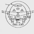
Tuning antenna circuit: 1 - direction "north"; 2 - direction "south"; 3 - azimuthal direction; 4, 7 - angle at the installation site relative to the location of the satellite; 5 - television satellite; 6 - satellite signal
Traditionally, "plates" are placed on the wall of the building next to the window opening, or the installation is done on the side of the wall, which is part of the balcony (loggia) structure.
The instruction prohibits installation directly inside the balcony area, especially the glazed one. Also, the equipment should be installed at points where there is no possible fall of precipitation in the form of snow and ice from the roof.
Step-by-step instructions for mounting the plate
It is first necessary to assemble the satellite antenna structure as this procedure is described in the attached instructions. As a rule, antennas are delivered unassembled. Therefore, the structure must be assembled using the supplied accessories.
Step #1 - Attaching the Antenna Bracket
Again, given the work with a proprietary product, where all installation elements and components are designed for the appropriate load, work is being done to install anchor bolts in the wall of the building.

One of the options for antenna brackets that are used for reliable, sturdy installation of a satellite dish. Initially, a support pipe is attached to the wall, and the antenna bracket is directly attached to the pipe
This work is done in a standard way, using a tool for working with concrete. After the introduction of the anchors, a support rod is attached to the installed anchors, and a metal bracket is attached to the rod.
Step #2 - Installing the Antenna Converter
The installation of a preliminary signal amplifier - converter, is carried out strictly according to the instructions, where all the subtleties of the placement of this component are noted.

The converter itself should be fixed in the support ring in such a way as to ensure perfect tightness of the device. Even a slight penetration of moisture inside threatens to disrupt the operation of the device.
Step #3 - Connecting the Cable to the Converter
At the current stage, the cable, which is usually also included in the kit, is connected to the converter module. The connection is made by means of the special “F” connector included in the scope of supply.

An example of a well-connected cable on the side of the converter. Well-executed sealing of the connection area is clearly visible, which will ensure stable operation of the amplifier for a long period of time
The connection area must be carefully sealed, for example with silicone sealant. The cable from the point of inclusion is gently and effortlessly pulled through the body of the converter holder rod. It is fixed at regular intervals with plastic ties or in another way.
Step #4 - Fixing the Satellite Dish
The prepared “plate” is installed on the bracket, while the adjusting screws are not tightened to the stop - they are left loose.
This approach is necessary for the simple reason that further (after installation) the procedure for fine tuning to the satellite will follow. Accordingly, the “plate” will have to be moved both vertically and horizontally.

Installed, fully custom-made household "dish", ready to reward its master with a high-quality television picture received from a satellite
Separately, it is worthwhile to instruct on the installation of the F-connector on a coaxial cable. This operation has its own characteristics. The end area of the cable (approximately 15 mm long) must be freed from the first insulating layer.
But you need to remove the insulation, taking into account the integrity of the screen braid present under the insulation layer. Then the second layer of insulation is removed over a length of about 10 mm. This releases the central copper core. Next, the connector is screwed onto the cleaned trailer until it stops, passing the copper conductor into the corresponding hole.
How to adjust the installed antenna?
Usually, the “dish” installation instructions contain a table where information on azimuth and angle is indicated - setting parameters in the direction. The parameters are indicated, as a rule, for the area where large settlements are located.
You should select the nearby territory from the list and take the parameters of the angle, azimuth for setting. Further, according to these parameters, set the antenna mirror by moving the "dish" in the vertical and horizontal planes.
This will be the "rough" setting. After which the antenna cable is connected to the receiver, and the receiver, in an appropriate way (also through the connecting cable) to the television receiver. Then it remains only to adjust the parameters of the angle and azimuth, achieving the highest quality picture on the TV screen.

Tuning table based on the location of large settlements, which indicates the preferred angle and azimuth parameter for the direction of the antenna
Any receiver by default has a service for monitoring the level of the received signal. Using this functionality, you can configure the equipment with high accuracy. However, weather conditions can make adjustments to the setting. Therefore, it is recommended to perform tuning activities under conditions of a clear, cloudless sky.
Having achieved the emergence of a stable, strong enough control signal on the TV screen, the mirror mounting nuts on the bracket are screwed up to the stop. The equipment on this is considered installed and configured.
Further, they are already moving to the usual user viewing using access cards or through free available channels. How, choose channels and open access - all this is in the user manual.
If a dish is installed in the country for regular viewing of TV programs, most often the signal received by the antenna needs to be improved due to the significant remoteness of the repeater. In this situation, it will help, with the rules for choosing which the article we recommend will acquaint you with.
Conclusions and useful video on the topic
Below is a video material where the home master explains from personal experience all the subtleties of installing the “plate”.
Accordingly, the whole process is filmed on a video camera, so the reader is clearly shown how to install a satellite dish with his own hands:
Despite the visible and invisible difficulties that manifest themselves in the process of installing a satellite "dish", it is quite possible to cope with such work with your own hands. The main point is the scrupulous collection, processing of up-to-date information and, of course, a careful study of the accompanying instructions.
If you want to use satellite TV, and buying a large diameter antenna is too expensive for you, then this article will help you. It describes several options for how to do it yourself, and perhaps this will lead you to the optimal solution to the problem.
Starting to design a parabolic antenna for satellite television, it is necessary to take into account the irradiator included in the converter and its parameters. There are two manufacturing options: using gluing on a matrix or soldering a mesh, and the first allows for ease of control over the form during its manufacture, the second has less weight and windage.
The parameters that characterize the antenna are its diameter, the shortest distance from the focus to the reflector of the antenna (the so-called mirror depth and the aperture angle under which the mirror plane is visible.
Thanks to these values, the antenna parameters are calculated, then transferred to graph paper, and a parabola is built. It must be glued to a sheet of steel, the thickness of which should be five millimeters, and cut out. This is how a knife is obtained, after which you need to pick up a bearing and a rod. In this case, it is necessary to shorten the knife by a distance equal to half the diameter of the rod, and weld it to it. To get a satellite dish with your own hands, you need to make a frame from a steel bar (with a diameter of eight to ten millimeters) by welding. The ribs must be bent along the knife, the bearing must be welded into the top of the frame.
The antenna frame must be installed on a flat area. In its center, a pipe is installed vertically under the bearing. After fixing a washer on the bearing, which is slightly larger than its diameter, and equal in thickness to the future parabolic antenna, a knife is inserted into it. A thick concrete solution is applied to the frame. The resulting matrix dries for three to five days.
Starting the gluing process, do-it-yourself satellite dish is performed in several ways. To simplify your task, the product should be divided into sectors (from six to eight). For strength, the thickness of the reflector must be increased and reinforced with radial ribs made of steel wire. For gluing a parabolic antenna, glass fabric cut into strips is used and, first, automobile oil is applied to the matrix. A pipe is inserted into the washer. A washer is put on it, equal in height to the thickness of the reflector. Then a layer of resin and pieces of fiberglass are applied, which must be smoothed out to remove air bubbles. Cover the reflector with aluminum foil.
When creating a satellite dish with your own hands, you can use another option when forming a conductive surface. Why paints are applied to the reflecting surface of a parabolic antenna, which include metal-powder bases. For example, silver. Having formed the thickness of the reflector of the desired size, it is fixed with nuts.
There is an option to create an antenna from papier-mâché, when newspapers passed through a meat grinder are used as a filler. Glue is added to them and the composition is applied to the matrix.
Before you start implementing the project - a satellite dish with your own hands, you should consider several factors affecting its operation. After all, the lower floors of the building, reinforced concrete, which the windows are equipped with, can interfere with the functioning of the product.
There are different possibilities for making an antenna with your own hands: from beer cans, from a room antenna, from a copper cable. Or you can use an existing factory satellite dish and add a self-made satellite dish to it.
Glue sheets of A4 paper to the product with adhesive tape and lay out along the concave edge. From coarse fabric, cut 5 pieces for the antenna in the shape of its mirror. Put them on a plate in turn, grease with glue. On the resulting frame, treated with glue, after a day, put culinary foil. On the reverse side, glue again with a cloth. A plastic water pipe is suitable for the converter. The antenna mirror must be covered from a spray can with a layer of paint of small thickness.
To improve 3G, 4G, or WiFi reception, a parabolic antenna mirror is used. Since the Russian loves halava, he is increasingly looking on the Internet for how to make a "satellite dish" at home. Let's look at a couple of options together.
Watch the video to get started...
If the Internet is not very fast or not "unlimited" and cannot (or does not want to) watch the video, then I will describe the technology in my own words.
At the beginning, they show how to cut an even circle from the "plex", then the lid is taken from the pan (it has the shape of a parabola), placed in the oven along with the plexiglass blank. When heated, the "plex" takes the shape of a parabola. Then you can paste over with thick foil and the mirror is ready.
Although the video gives an example of making a parabola, the downside is that the diameter is small for the antenna. Although there are larger ovens, in short, we received information for reflection, then only your imagination will help ...
That was one option, let's look at another.
To begin with, you need to try this option on a piece of paper with a scale of 1:4 or 1:5.
So, to get mirrors with a diameter of 80 cm, you will need cardboard 100 X 100 cm. With these dimensions the focus of the mirror is 13 cm.
Let's break it down like this:
draw on 16 identical sectors (22.5°) and 4 circles with radii r1, r2, r3, r4:

Circle radii:
- r1 = 75 mm
- r2 = 254 mm
- r3 = 400 mm
- r4 = 528 mm (this radius is out of square, cut to square)
There will be a bend along these circles.
Now you need to make cutouts along 16 lines with the distance between the petals s1, s2, s3, s4:

Distance between petals:

- S1 = 0mm
- S2 = 11mm
- S3 = 29mm
- S4 = 50 mm
According to this blank, you can draw on an estimated sheet. Connect the edges and the mirror for the parabolic antenna is ready.
Option 2
In this article I will describe an acceptable way to make a satellite dish with your own hands. I read on the Internet (I don’t remember on which site): you need to take an antenna from a neighbor, put a wire in it and fill it with plaster. Imagine its weight, and its wind resistance...
So, here we will look at how to create the parabolic "mirror" itself, and which antenna you will hang up (wifi, 3 | 4G) is up to you.
Alternatively, you can do this:
 Take a galvanized sheet and make eight cuts, then connect the petals together.
Another variant. We need a big ball:

We make the first circle from the wire with the diameter that you need and put it on the ball:
 K1-K4 - circles made of steel wire with a diameter of 4-6 mm. Draw lines under the circles with a marker.
Then, we connect the circles with aluminum thick wire crosswise, remove the product. Instead of aluminum wire, one by one we replace it with steel and weld it by welding.
It should turn out like this:
 Lap 4 should remain open, where the irradiator stand will run. The rest, you need to stretch the wire - make a grid.
As an option, a mirror can be covered with a finished aluminum mesh:


Focus - this is the location of the irradiator (antenna) at a distance from the center of the satellite dish. This distance depends on many factors. For example: frequency, opening "mirrors".
A parabola is like part of a ball, and the focus of the ball is in the middle.
 If the antenna is made like Ant3, then the focus will be at the level of the antenna itself, etc.
Consider circle diameters.
Now about the frequency. Focus from frequency is calculated by a formula that takes into account the frequency itself and the diameter of the mirror. Since it is not known what diameter your "plate" will have, it is better to find the focus experimentally.
Let's say you want to install Kharchenko's 3G antenna,
fasten it to the shaft and slide it into circle 4. Start the MDMA type program (in dB it shows the signal level) and move the shaft slowly towards or away from the antenna.
In conclusion, I would like to say about the diameter. In practice, the gain on the Kharchenko antenna and a satellite dish diameter of 90 cm reached 40 dB.
 Carrying out rescue operations in damaged (destroyed) buildings and structures
 Autocad mechanical setting dimension styles