How to fold polylines in autocad. Lessons on the program AutoCAD. – How to convert a line segment to a polyline
A polyline is a complex primitive consisting of one or more linear and arc segments connected to each other. All these segments are a single object.
To draw a polyline on a tab "Home" in the panel "Drawing" choose a team "Polyline". If you prefer to use the command line, then you need to type in it the command PLINIA(for English versions of the program _pline) and press Enter.
First of all, we set the starting point with the cursor, or specify its coordinates. If now we sequentially indicate different points on the plane, we will get a polyline, which consists of straight segments. For example, let's build an arbitrary polygon.

To close our polygon, right-click to call up the context menu and select the command "Close"(in English versions close). You can close the contour by simply specifying the end point with the cursor, but you will agree that it is more convenient to do this automatically.

If you now click on any of the sides of the constructed figure, it will be selected for editing as a single object.
Now let's take a look at the options you may have already noticed by right-clicking the context menu. Press the button again "Polyline", specify the starting point and call the context menu.
The first option on the list is "Arc".

This command puts us in the mode of constructing polyline arc segments. Create a new shape using the button "Arc".

We complete the construction by pressing the button "Close".
Consider another option from the context menu "Width".

This command allows you to set the line thickness for each subsequent segment. When building, the system offers to set the initial and final thickness, which allows you to create tapering and expanding segments. When a constant thickness is needed, the same start and end values are set. For example, let's build an arrow. We press the button "Polyline", specify the starting point and call the context menu, select the command "Width". For the first segment, we set the initial thickness equal to zero, final 10 mm(after entering each of the values, press the key Enter). By simple stretching, we set the length of the arrow.

Calling the command again "Width" and enter the values of the initial and final thickness 3 mm stretch to desired length. We complete the construction by pressing the key ESC.

The "Halfwidth" option is similar to the option "Width", with the only difference being that it sets the half sizes of the initial and final thickness of the polyline.
Using the option "Length" you can specify the length of the next polyline segment exactly.

Keep in mind that the line will be built in the same direction as the previous one. We will not give an example, since the constructions are simple, experiment on your own.
In the next lesson, we will consider some features of constructing polyline arc segments.
If you have any questions you can ask them
Pltools answers all the questions that you may have when working with polylines and 3d polylines. Convert, optimize, referral, and more. One convenient, small panel contains functionality that, in theory, should be in AutoCAD by default.
The history of this project is very old. Actually, it was first published in September 2006. Since then, the set has undergone a number of changes that improved it without changing it cardinally. This toolkit is the fruit of the collective creativity of the authors and participants of the forums autocad.ru And dwg.ru.
Separate developments for working with a polyline were brought together, a common interface and help were added to them. The new commands complement each other extremely well, and the interface for working with them turned out to be simple, intuitive and visual.
It must be admitted that this is the product, having worked with which, you do not understand how you lived without it before. I will say more - two teams from the set permanently settled in.
With this set, polylines unleash their potential, turning into a powerful and versatile tool. Area calculation, space modeling, 3D graphics, everything becomes easier, clearer and faster.
Where to download PLTOOLS
You can download it here: http://dwg.ru/dnl/607 in 2014 we added support for the Ribbon.
Purpose of PLTOOLS
A set of programs for working with polylines.
Programs and panels are taken from here
http://www.autocad.ru/cgi-bin/f1/board.cgi?t=23073xg
http://www.autocad.ru/cgi-bin/f1/board.cgi?t=20156yO&page=4
http://dwg.ru/forum/viewtopic.php?t=8509
http://www.autocad.ru/cgi-bin/f1/board.cgi?t=27884PF
http://autolisp.ru/dwlsp/20
http://dwg.ru/forum/viewtopic.php?t=8699
http://dwg.ru/forum/viewtopic.php?t=8722&postdays=0&postorder=asc&start=15
http://www.caddzone.com/free.htm
Used program codes
Alesey Kulik aka kpblc (http://autolisp.ru/)
Evgeny Elpanov (http://elpanov.com/)
Zuev Sergey aka ShaggyDoc
HELL. Sheinkman aka Lazy
Vladimir Gromov aka Profan
Good ideas from Alexander Kosov aka KAI
Lee Mac (http://lee-mac.com/)
Put together by Vladimir Azarko (VVA)
list of files
BMP- a folder with pictures for buttons
LISP- folder with source lisp file
pltools.mns- menu for loading in AutoCAD up to 2005 inclusive
pltools.cui- menu for loading into AutoCAD from 2006 inclusive
pltools.cuix- menu for loading in AutoCAD from 2010 inclusive
pltools.chm- help file
pltools.fas- compiled lisp file
pltools.dll— library of images for buttons
readme.txt— description of the project.
Certain AutoCAD commands (Edition 06/17/2014)
- PL-JOIN-Merge selected polylines
- PL-VFI-Insert vertices in the selected polyline at the intersections with
specified polylines, lines, arcs - PL-JOIN3D-Merge 3D polylines
- PL-A2L-Replacement of a linear segment in a polyline with an arc segment.
- PL-L2A-Replacement of an arc segment in a polyline with a linear segment.
- PL-DIV-Splits the selected polyline segment into the specified number
- PL-DIVAll-Splits all polyline segments by the specified number
segments or after a specified distance - PL-VxAdd-Adds a new vertex to the polyline
- ENTREVS-Reverse object
- ENTREV-Reverse objects (multiple choice)
- PL-CW- Reverse selected polylines clockwise
- PL-CCW- Reverse selected polylines counterclockwise
- PL-VxRdc-Deleting polyline vertices that lie on the same line
- PL-VxDel-Delete selected vertex
- pl-VxOpt-Remove matching vertices from a polyline
- PL-NoArc-Approximation of polyline arc segments
- PL Clone-Building a polyline by copying its segments
- PL-VxMove-Move polyline vertices
- PL-Vx1-Change the beginning of the polyline
- ConvTo2d-Convert linear objects to 2D polylines
- ConvTo3d-Convert linear objects to 3D polylines
- MPL-Construction of the middle line
- R3P-Rectangle by 3 points
- PL-P90-Drawing polyline segments perpendicular to each other
- PL-CSE-Combining 2d polylines by primitive
- PL-SgWidth-Change polyline segment width
How to use pTools
- Put the files in the folder specified in the path to the auxiliary files
(Tools->Settings->Files->Auxiliary Files Access Path)
For example: " C:\Distribution\Add-ons\Polylines\Pltools« - team _menuload loading pltools.cuix
- A tab will appear on the ribbon. Pltools. The first panel includes all commands, in the remaining panels the commands are divided into categories. tab Pltools adapted for workspaces "Drawing and Annotations" And "Classic AutoCAD"(if the latter uses tape). Also in the workspace "Classic AutoCAD" classic panels will appear on the screen. If you have hidden any of the standard tabs, they will pop up again. I'll have to hide again.
Actually, in order to show how fast and trivial it is, I recorded a small video lesson.
Spline team, Polyline team
SPLINE command
http://www.autocad-profi.com/spline.php
Input: Classic AutoCAD: from the Drawing command bar - from the Drawing drop-down menu. On OSD versions, from the DRAW 1 submenu. Ribbon variant: from the Draw command bar. Purpose: builds smooth curved curves passing through given points.
Peculiarities: the constructed curve can either pass exactly through the given points, or deviate from them by a set amount, for which the Tolerance option is entered and a request for the deviation value follows. The constructed spline can be combined with another spline with the JOIN editing command (see 8.15) provided that the end points match. One spline can be attached to one point. The number of consecutively connected splines is not limited. If splines have two common points, then they form a closed contour. Team Termination– right-click, after which the command asks for the direction of the tangents at the start and end points of the curve.
Subcommands:
1. For a closed curve (Close option), the direction of the common tangent is requested. close(close) - the last point of the spline will be connected to its first point. In this case, you will be required to specify the direction of the tangent At the starting point of the spline - Specify tangent: (Indicate direction:). You can do this with the mouse. If you just press “Enter*” again, then in this case the direction of the tangent will be taken as it is by default.
2. Tolerance (Fit Tolerance)- allows you to specify the permissible deviation of the spline from the given points. By default, the tolerance is zero. Increasing the tolerance is used to build smoother splines. After specifying the tolerance, you will return to the mode of further spline construction.
Usage: in engineering graphics, the SPLINE command can be used to draw cliff lines. With the help of splines, you can draw beautiful shapes with smooth transitions. Splines are especially useful in design work.
POLYLINE command
https://drawing-portal.com/glava-sozdanie-ob-ektov-v-autocade/poliliniya-v-autocad.html
Input:
Classic AutoCAD: from the command panel Drawing - , from the falling
the Draw menu. On OSD versions, from the DRAW 1 submenu.
Ribbon option: Home => Drawing.
Purpose: the command draws a complete primitive in the form of a polyline, arc or circle, a combination of line segments and arcs.
Peculiarities: The command is similar to the INTERCEPT command in that it also draws a line segment or a polyline. Polylines created by the Pline command consist of straight-line segments that are perceived by the AutoCAD system as a single object. Polylines created by the Line command consist of straight line segments (segments), each of which is a separate object.
Usage: The polyline is widely used in two-dimensional design and 3D modeling in AutoCAD, because the set of functions (parameters) of this tool is large.
In 2D design The most important feature of AutoCAD polylines is that we can extract data from objects created from polylines and display them using fields.
In 3D modeling AutoCAD's most important feature of polylines is that we can convert flat objects from polylines into 3D objects using special commands.
Also, a polyline is used to draw arrows, as well as to obtain closed contours.
The team has a developed system of options and requests. This is one of the most "talkative" teams.
Polyline construction modes in AutoCAD
In AutoCAD, there are two modes for constructing a polyline:
linear (line)- allows you to create straight polyline segments. In this mode, working with a polyline becomes similar to working with the Segment tool;
arc- allows you to create arc-shaped polyline segments. In this mode, working with a polyline becomes similar to working with the Arc tool.
When enabled, the command prompts for the first point. After specifying it on the command line, a message appears about the current state of the line thickness and a number of queries about the further operation of the command:
The current polyline width is 0.0000.
Pick the next point or [Arc/Close/Halfwidth/Length/Undo/Width/]:
The second line contains options (queries) used in the further work of the command.
After finishing work with any option (except Close), the command is ready to continue working and the following prompt is displayed on the command line:
Pick the next point or [Arc/Close/Halfwidth/
Length/ Cancel/ Width/]:
Description of options
close– draws a segment that closes the constructed polyline (connects the last point to the first) and terminates the command. If the last segment was an arc, then a closing arc is built. Sometimes this causes certain difficulties. In this case, draw a short line segment before closing the polyline.
Cancel– deletes the last constructed polyline segment; when applying the option several times in a row, the corresponding number of segments is deleted.
Width– setting the line width. When this option is selected, additional prompts follow:
Initial Width<0.0>:
This request must be answered by entering a new line width from the keyboard.
or by pressing the enter key, accept the current value. When you enter a new value, it appears in the query string after the colon.
For example, a value of 0.8 was entered. This is followed by a new request:
End Width<0.8>:
When drawing a line of constant width, the enter key is pressed. If you move the mouse instead, the program will perceive the cursor offset as the value of the final width of the polyline, which leads to unexpected consequences. The entered width will be used for all subsequent occurrences of a command in a given file up to its explicit redefinition.
ATTENTION: if the line thickness is zero, the polyline is drawn with the thickness set by the command LINE WEIGHT , and for any thickness other than zero, the LINE WEIGHT settings are ignored.
The command allows you to draw a line of variable thickness, which is used, for example, when drawing arrows , for which it is enough to set the initial thickness of the polyline equal to 0.0, and the final one, equal to the width of the arrow.
Conversion to a polyline may be needed when drawing in AutoCAD for those cases when a set of separate segments needs to be combined into one complex object for further editing.
In this short tutorial, we'll look at how to convert simple lines to polylines.
How to convert to polyline in AutoCAD
1. Select the lines you want to convert to a polyline. You need to select lines one at a time.

2. At the command line, type the word "PEDIT" (without quotes).
In newer versions of AutoCAD, after writing the word, select "MPEDIT" in the command line drop-down list.
3. To the question "Should these arches be converted to a polyline?" choose the answer "Yes".
Everything. The lines have been converted to polylines. After that, you can edit these lines as you like. You can connect, disconnect, round corners, chamfer and more.
Thus, you have seen that converting to a polyline does not look like a complicated procedure. Use this trick if the lines you've drawn don't want to be edited.
AutoCAD Tutorial. Polylines in AutoCAD.
General rules for constructing polylines.
The AutoCAD system provides for the construction of objects such as polylines. These lines, in comparison with the segments created by the Line command (Segment), are more universal. They have a number of features:
You can directly set the thickness of the polyline, while for the line segment you cannot. Moreover, the thickness of the polyline can vary along its length.
Polylines can include multiple segments. In this case, all segments are created by one command and are perceived by the AutoCAD system as a single object. For example, an arbitrary polygon can be built as a polyline, and it will be perceived as a single object. If such a polygon is constructed using the Line command, then each side of it will be a separate object.
Polylines can include arcs. Examples of polylines are shown in the figure below.
To build polylines in AutoCAD, the PLine command is intended. You can call it in three standard ways:
1. by clicking on the button on the Draw toolbar or on the Home tab of the tool ribbon;
2. from the menu bar Drawing (Draw) -> Polyline (Polyline);
3. by entering into the command line: _pline (or PLINE).
Basic technique for constructing polylines.
After calling the PLine command, you will be required to set the starting point for construction. This will prompt you on the command line:
Specify start point:
Starting point:
By specifying the first point, you will receive the following query:
Current line-width is 0.000
Specify next point or :
The current polyline width is 0.0000
Next Point or [Arc/Halfwidth/Length/Undo/Width]
In response to it, you can either specify the next construction point - and then a segment of the current width will be built, or select one of the options. Let's say you chose the first option and specified the second construction point. The next query will be the same as the previous one, only the Close option will be added:
Specify next point or :
Next Point or [Arc/Close/Halfwidth/Length/Undo/Width]:
Accordingly, in the future, you can either continue the construction of straight segments of the polyline, or select one of the options. Now let's take a closer look at what these options are:
Arc- allows switching to the mode of constructing polyline arc segments.
Close- closes the polyline, that is, connects its first and last points. On this command execution PLine ends. This option becomes available after you have drawn at least one polyline segment.
Width- by selecting this option, you can set the line thickness for constructing subsequent segments of the polyline. In this case, you will be prompted to enter two values in turn - the initial and final width (which allows you to build narrowing or expanding polyline segments). It is convenient to build arrows in this way. If the width should be constant, then specify both of its values the same (Fig. 6.2).
Halfwidth- this option is similar to the previous one and differs only in that it sets the half sizes of the initial and final width of the polyline (Fig. 6.2).
length- thanks to this option, you can precisely set the length of the next polyline segment, which will be AUTOMATICALLY built in the same direction as the previous one (or tangent to the previous arc, if the previous segment is an arc).
Cancel (Undo)- serves to delete the last constructed polyline segment.
Construction of an arc as part of a polyline.
The methods for constructing arc segments of a polyline are similar to the methods for constructing arcs with the command Arc (Arc). As mentioned earlier, in order to proceed to the construction of an arc segment of a polyline, it is necessary for the command PLine select the Arc option in the command line (Arc). After that, a prompt will appear on the command line:
Specify endpoint of arc or :
Arc Endpoint or [Corner/Center/Close/Direction/Halfwidth/Linear/Radius/Second/Undo/Width]:
In response, you can either specify the end point of the arc - and the construction of the arc segment of the polyline will end there, - or select one of the options. Of particular note is the option Linear- it returns to the mode of linear construction of polyline segments. All other options are used to select the method of arc construction or set its parameters:
Angle- sets the internal angle of the arc segment.
Center (CEnter)- sets the center of the arc segment.
Close (CLose)- builds an arc segment that closes the polyline.
Direction- by default, the arc is built in such a way that the previous segment is its tangent. This option allows you to specify a different tangent.
Radius- sets the radius of the arc segment.
Second (Second pt)- allows you to set the second point of the arc segment to build it by three points.
Halfwidth (Halfwidth), Width (Width), Cancel (Undo)- identical to the options of the same name for the linear segment.
At the end of the review team PLine I would like to note that it is very convenient for a number of specialized constructions.
For example, quite often designers use this command when drawing printed circuit board drawings.
Sign Up For The Newsletter Right Now!
And Get Free
Educational Videos Lessons
By AutoCAD To your E-mail!
Just Enter Your Data In The Form!
![]()
|
|

 Modules for digital television
 Tricolor TV - receiver software update
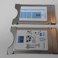 Satellite receiver or satellite TV input ci common interface