What is ethernet connection technology. Metro Ethernet - services for telecom operators in the "non-marketing" sense
When working in a home network, the provider's point of presence is located right in your house or in a neighboring house. Access equipment, to which customers directly connect, are distributed in basements, attics, electrical panels. In most homes, these facilities are not guarded or have poor protection against intrusion, so theft of active equipment (switches, access points) and even passive equipment (cables) is a common problem. Malefactors open any safe boxes, do not disdain any trophies. This circumstance has twofold consequences. On the one hand, the cost of purchasing equipment, one way or another, is paid by the clients. On the other hand, the operator is forced to use cheap, non-professional equipment. If, nevertheless, expensive equipment is used, it is located in the apartments of some clients. This approach protects well against theft of equipment, but makes it impossible for the repair team to access it, for example, if the client has gone on vacation or to the country. As a result, it turns out that the quality and reliability of the provision of services suffers greatly, the time for troubleshooting can range from one day to several weeks.
Of course, a lot depends on the provider itself and its contractors. If the network is created by “craftsmen” (your neighbors), the quality of the cabling can be very poor: it may be the first network in their life, and they think that laying the network in a residential building is as easy as screwing in a light bulb. Such installers, without raising an eyebrow, make “twists” on wires that are destructive for high-frequency signals, without realizing the danger from lightning discharges, pull unprotected overhead lines, lay unshielded cables in elevator shafts, ignoring the harm from strong electrical interference. But even if the installers of your provider know their business well, the network they have made is not protected from knock-offs from competing firms, which can easily confuse their own and other people's wires.
Thus, Internet access problems usually have an internal cause. If, in the event of failures of external channels, the provider can quickly take action, then the client himself must report a breakdown within the network. Only after confirming the malfunction is an outfit given to the repair team, which may already have several calls for that day.
Home networks are not hopeless, of course. Unnamed amateur providers are being ousted by large operators with a staff of skilled installers around the clock technical support by multichannel telephone, modern accounting system. Many providers offer preferential or free connections to those who have already connected to a competitor. Therefore, without special costs, the user can work in several networks one by one, compare the quality of services and "vote with a wallet." Thanks to competition, only the best providers survive, and Internet access via a home network remains one of the most economical and convenient ways to connect.
The main advantage of home networks is the high speed of information exchange with neighboring computers. Usually, the exchange within the network is not subject to tariffication. This allows you to receive tens of gigabytes of information with minimal costs (usually by a pirate method): for example, a video High Quality may take only two to three minutes to load. In home networks, thousands of file servers store almost the entire archive of world cinema and the music industry, hacked computer programs and electronic books... Fans of multiplayer games have the opportunity to arrange network battles with their neighbors without feeling the slightest delay in the actions of their character.
The second legal problem with many home networks, after copyright infringement, is the violation of communications law, that is, the existence of properly unlicensed home networks. Ask your provider about the license for the network specifically in your house, if you do not want any surprises in the future: the illegal network can be disbanded at any time, and no one will return the cost of connection and the prepaid subscription fee to you.
Despite the fact that the connection through the home network belongs to the class of "permanent" connections, that is, they do not require dialing, initialization of a secure communication session may be required to enter the network, similar to the establishment of a regular modem connection. The same applies to the speed of working with the Internet: despite the fact that channel the speed can reach 100 Mbit / s, beyond the most local network most likely, there will be a forced limitation in accordance with the selected tariff.
Ethernet
Ethernet technology("Network communication over the air") was developed to create high-speed office networks. Now, due to the reduction in cost, office technologies have become available to home users as the cheapest and most reliable means of organizing a home and even an intra-apartment network.
From the point of presence of the provider, cables run throughout the house. Branching is provided using hubs or switches. Concentrators are the simplest electrical signal repeaters that mix signals from several computers into one heap. At the same time, only one computer can transmit data at a time (Fig. 1a).
Rice. 1. Simultaneous transmission in the network with hubs and switches
If there are many computers in such a network, the exchange rate between them will be far from the nominal. Vice versa, switches demarcate signals different computers allowing multiple computers to simultaneously send and receive data (Figure 1b). Moreover, the switches remove the restriction on the maximum distance from the provider's point of presence. Now cheap hubs and cheap switches are almost equal in price, so the use of hubs can be considered a sign of excessive stinginess, and the stingy one, as you know, pays twice.
From the access point to the apartment, the cable is pulled by the installers. In the apartment - you yourself, or the same installers, but for an additional fee. It is necessary to calculate in advance how long the cable is needed so that it can reach the computer even after a small rearrangement. The total cable length should not exceed 100 meters.
The first home networks were built on the basis of 10 Mbps technology (IEEE 802.3, 802.3i and 802.3a standards). Now the most popular standard is 100 Mbit / s, it is also Fast Ethernet or 100Base-TX (IEEE 802.3u), backward compatible with the old one. This channel speed provides a file transfer rate within the network at the level of 5-10 MB / s; with increased network activity, the transmission speed may decrease. Modern technologies, for example, IEEE 802.3ab, allow you to get up to 1000 Mbps over an ordinary cable, more efficiently using its signal lines. However, the use of such equipment on the scale of a home network is ineffective, since it is noticeably more expensive, and there is still little real need for ultra-high speeds.
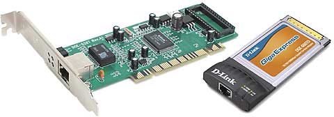
To connect, a conventional network controller is enough, which is built into most modern computers... If you do not have this, you can purchase a PCI card (Fig. 2), starting from 100 rubles, but do not expect to reach the speed of 100 Mbit / s on this product: this is like a "win-modem", that is, a minimum of hardware and a maximum load on CPU... More or less high-quality devices start at $ 15.
Rice. 2. Ethernet adapters for PCI and Cardbus buses
Ethernet networks often suffer from a lack of user authentication mechanisms. In other types of networks, where unauthorized connection is easy to make, security is thought of even at the stage of standards design. And since Ethernet was designed for office applications that are user-friendly and require physical access to the cable to connect, no built-in security is provided. The problem is solved by using partial or full encryption between the user and the Internet gateway (see). Small providers and amateur providers save on implementing full-fledged protection and either use alternative homemade products or do not control their network at all, that is, any neighbor in such a network can pump files for a hundred or two dollars on your behalf.
Wi-Fi
Wireless networks, in particular Wi-Fi (Wireless Fidelity), have one distinct advantage: no wires are required in your apartment. The computer can easily move from one place to another, which is especially valuable if it is a laptop or PDA. At the same time, the provider's trunk cables can still be wired around the house, but in much smaller quantities. Wireless access points are used instead of switches (Figure 3).
Rice. 3. Wireless network structure

The most common equipment is compliant with IEEE 802.11b and 802.11g standards. Both standards operate in the 2.4 GHz frequency band, allowing the choice of the most favorable frequency channel from several frequency channels. Radio signals are steadily caught at a distance of up to 400 m with a line of sight outside and up to 100 m in a building. As for radio telephones, reinforced concrete walls are not an impenetrable obstacle for them, but any obstacle overcome by the signal reduces its strength: any walls, doors, refrigerators and washing machines, microwave ovens located between the transmitter and receiver do not interfere, but weaken the signal (Fig. 4). Additional antennas can improve the signal quality if your equipment allows them to be connected. And if the signal is weaker, if the signal-to-noise ratio is lower, then the speed is lower.
Rice. 4. Signal attenuation with distance

Speed is one of weaknesses wireless connection versus Ethernet. A wireless access point is the same hub, only with an antenna instead of wires; speed is also shared among all clients. Moreover, unlike Ethernet, declared the speed (11 Mbps for 802.11b and 54 Mbps for 802.11g) is practically unattainable even when there is only one client. First, this claimed speed is the theoretical maximum given the compression algorithm used, and large files are usually already compressed. Secondly, as mentioned above, the speed decreases with distance: probably at least 15 m from the access point to your computer and two or three walls. Therefore, the real speed should be expected in the region of 35% of the declared one, but it can be 10% or 60%. This also applies to the tempting 108 Mbps promises: real speed will not exceed 50 Mbit / s, and then only if equipment from the same manufacturer is used. In other words, wireless connection should only be used if you are not going to exchange large files and play with neighbors.
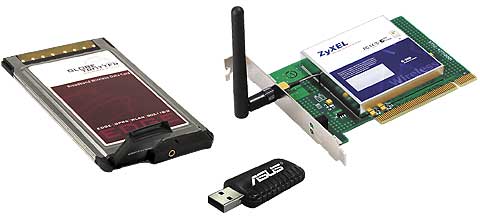
To work wirelessly, you need a network controller of the appropriate standard (802.11b / g). Now they began to be built into dear ones motherboards desktops as well as laptops. Separate wireless network card for PCI slots or PC Card can be purchased starting at $ 30. external adapters with a USB interface, including USB dongles (Fig. 5).
Rice. 5. Wi-Fi adapters for Cardbus, USB and PCI buses
Rice. 6. Portable detector Wi-Fi networks, cordless phones, video cameras and other household radio transmitters
The central problem wireless networks- security. Without proper security measures, your traffic can be intercepted by almost anyone. For this he does not have to enter your apartment or install bugs - it can be an inconspicuous person with laptop, located on a bench in the yard, or a neighbor's son - an aspiring hacker. At the dawn of the spread of radiotelephones, they used to call abroad by connecting to someone else's phone. Radio network scanners can now be purchased for as little as $ 50 (Figure 6), and it is not so easy to detect and prove the guilt of an attacker.
The basic cryptographic security standard WEP (Wired Equivalent Protection) has over time been recognized as insufficiently reliable, therefore it is recommended to purchase devices supporting the WPA (Wireless Protected Access) standard, which has already been developed as WPA2 (IEEE 802.11i standard). Devices from some manufacturers allow support for new standards through a simple firmware update, while other devices are not available for upgrades, and you will have to buy new hardware to support new technologies.
Security methods such as WEP and WPA encrypt data only when transmitted between wireless devices - between your network card and the access point. These technologies do not apply to all other data routes.
HomePlug
As a transmission medium, the most common household electrical network with a voltage of 220 volts (in English, plug - "plug") is used. In fact, the computer receives power and connects to the Internet through the same outlet. No additional cables required. Since the entire network infrastructure is already in place, the labor required to connect is minimal.
For information transmission, the frequency range of 4.3-20.9 MHz is used. Since the power grid is adapted for frequencies of the order of 50 Hz, the signals on high frequencies decay rapidly with distance. Not as fast as with wireless transmission but the wireless signal travels along the shortest path, and the wiring can have an ornate structure. Under ideal conditions, HomePlug signals have optimal power at distances of up to 100 m, the maximum length is 300 m.In the real world, communication is limited by strong interference from various electrical appliances: electric stoves, washing machines, hair dryers. To adapt to existing conditions, the frequency range is divided into 84 channels, any of which can be turned off if it detects interference or poor signal transmission.
Any devices in the signal path - extension cords, circuit breakers, and fuses - degrade the signal quality. High-frequency signals poorly pass through transformers (including those in uninterruptible power supplies), surge protectors, and electricity meters. Sometimes special bypass connectors are required to overcome these barriers. Every HomePlug device is protected against lightning strikes: if an overvoltage occurs, it may short circuit inside, but your computer will remain unharmed. Mains voltage is not required for communication, but may be required to power the HomePlug devices themselves.
The HomePlug 1.0 standard declares support for transfer rates up to 14 Mbps. According to the survey results, in real conditions 80% of users received 5-6 Mbit / s and above, in 98% of cases the speed was at least 1.0-1.5 Mbit / s. As with wireless access, the transmission medium is common for all users, which means that the speed is also shared among all active computers. Therefore, the network should be used only for Internet access, otherwise, due to internal exchange, it will become impossible to get high speed on the Internet channel. HomePlug 1.0 extension should be new standard HomePlug AV capable of speeds up to 200 Mbps, sufficient for demanding multimedia applications. There are alternative versions of the standard developed and promoted by individual manufacturers: for example, equipment for speeds of 85 Mbps. But such hardware has limited compatibility, and all devices must be of the same brand.
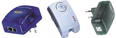
There are several types of HomePlug devices, differing in the type of computer interface and mode of operation. It can be a regular USB adapter (Fig. 7) or PC Card. Their mode of operation is called a "node". Such devices require additional drivers to be installed on the computer; unfortunately, only certain versions of Windows are often supported. Devices with a conventional Ethernet network interface can also operate in bridge mode, providing a bridge between the Ethernet network and the HomePlug network. All existing Ethernet devices are compatible with this mode: network cards, switches, network printers. Accordingly, no additional drivers are required. Models entry level cost about $ 70
Rice. 7. HomePlug adapters with Ethernet interfaces and USB
HomePlug technology has a limit on the number of concurrent devices. There can be no more than 16 of them in the "node" mode and no more than two in the "bridge" mode. If you add extra devices, they simply won't be detected. This greatly narrows the range of application of "bridges" in particular, and HomePlug technology in general, since no more than fifteen users can be connected using one wiring segment.
The threat of data interception on HomePlug networks is as real as it is on Wi-Fi networks. The encryption used consistently in HomePlug 1.0 is more resistant to cryptographic attacks than wireless standard WEP, but less secure than WPA. Alternative versions of HomePlug may have improved security mechanisms.
HomePNA
This type of connection got its name in honor of the developers - Home Phone line Networking Alliance. As in the case of HomePlug, existing wiring is used, only not electrical, but telephone. Unlike the DSL family of technologies, the provider's equipment is located right in your home, and not at the telephone exchange (where renting space is expensive and not allowed by every provider).
The used frequency range 5.5-9.5 MHz does not overlap either with regular telephone and facsimile communications, nor with digital (ISDN), nor with other signals (for example, with existing species DSL). Therefore, HomePNA does not affect your phone or DSL connection. Moreover, for HomePNA to work, a telephone line does not even have to be connected to a telephone exchange; however, if the line contains frequency filters, communication will be impossible or very difficult. Signal quality can also be affected by the quality of the cable wiring and the installation of telephone sockets.
Essentially, HomePNA is the same Ethernet. They differ only in the physical parameters of the signals (first level). Thus, HomePNA technology is suitable for networking not only in homes but also in offices; In order not to scare off business customers with the word “Home”, providers often refer to HomePNA as “HPNA”.
HomePNA 1.0 specification (ITU-T G.989.1 standard) allows simultaneous connection of up to 25 devices in one network segment - on one telephone line or using a dedicated hub. In this case, the length of the network should not exceed 150 m (which approximately corresponds to an area of 1000 m²) in normal mode or 500 m with signal amplification at the concentrator. The speed of 1 Mbps is shared among all users connected to the same segment; realistically it is possible to achieve transmission rates up to 950 kbps. There are also switches that allow you to combine several segments. Then the number of users can be measured in thousands, and each segment will have its own speed resource.
In version 2.0, the HomePNA standard has been seriously revised to provide speeds up to 10 Mbit / s and distances up to 350 m. significant reduction in speed. The number of devices in the network has been increased to 32. The use of switches is almost impossible due to interference between cables at high frequencies, so the only possible network topology is tire(all devices are connected to one long cable and share the speed with each other).
The latest version of HomePNA 3.0 offers speeds up to 128 Mbps and, in some devices, even up to 240 Mbps, selectively using the 2-30 MHz frequency range. The maximum number of users has been increased to 50, but as their number grows, the real exchange rate decreases.
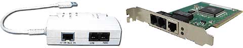
HomePNA USB adapters and PCI cards start at $ 80 (Figure 8).
Rice. 8. HomePNA + Ethernet Combo Adapters
Since HomePNA is a type of Ethernet, the technology does not provide built-in cryptographic data protection. For safe work it is necessary to use special means.
A proposal for the development of a network of operators is being considered
communication based on forward-looking Metro technologies Ethernet.
Three basic connection models are analyzed
based on virtual Ethernet connections (EVC) -
Point-to-point (E-Line), multipoint-to-multipoint (E-LAN),
Root-multipoint (E-Tree), as well as examples of them
practical application for solving problems of telecom operators.
NS The ubiquitous development of IP-based applications continually encourages users to find affordable and high-speed connections. Wired broadband access to the Internet using xDSL technologies or network mobile communications the third generation is a clear confirmation of this. But both in the case of xDSL and in the case of 3G, only one need can be satisfied - broadband Internet access for individual users, and with the provision of services without any quality guarantees. Another notable limitation of the applied broadband access solutions is a significant limitation of the bandwidth due to the physical capabilities of the "last mile".
Considering the development of the operator's network from an evolutionary point of view, the focus on services organized using Ethernet is expected and quite natural.
Ethernet as a technology, born for use in local networks, has undergone significant changes in the course of its evolution. It is important that at present the telecom operator, having implemented basic Ethernet services in the network, will maximally preserve the existing scenarios and algorithms for the interaction of its network elements and the related processes of management and tariffication of services.
An additional, but very important advantage of the proposed approach is new opportunities that open to the operator in the case of using the existing SDP (Service Delivery Platform) to organize services based on some basic configurations of the Ethernet network. First, it is the ability to flexibly and centrally manage key parameters in user profiles. Second, changing service designs without the involvement of SDP developers. Third, support for many different service configurations depending on key performance parameters.
Definition of services
Basic model of carrier Ethernet services Metro Ethernet Network (MEN ), shown in rice. 1. Customer Equipment (CE), connected to the network via a customer network interface(Unified Network Interface, UNI) using standard 100 Mbps and 1 Gbps Ethernet interfaces.

One of the key attributes of Ethernet services is virtual Ethernet connection (Ethernet Virtual Connection, EVC). Metro Ethernet Forum (MEF ) defined EVC as “the union of two or more UNIs”, where UNI is the standard Ethernet interface that defines the demarcation point between the user equipment of the MEN operator.
One of the key qualities of the E-Line is the ability
Organization of point-to-point EVC connections between UNIs,
similar to PVC Frame Relay.
_____________________________________________________
EVC has two functions:
1. Connects two or more user sites in order to ensure the transfer of Ethernet frames (frames) between them;
2. Prevents the transfer of data between user sites that are not part of the same EVC. This allows for the confidentiality and security of the transmitted data, similar to the permanent virtual connection (PVC) in Frame Relay or ATM networks.
Let's consider three main options for building an Ethernet network:
1. Ethernet line (E-Line) - Point-to-point;
2. Ethernet - LAN (E - LAN) - “Many-point-multipoint”;
3. Ethernet tree (E-Tree) - Multipoint root.
Point-to-point connection (E-Line)
E-Line is a point-to-point virtual Ethernet connection between two UNIs, as shown in rice. 2. In its simplest implementation, this type of connection can provide symmetric data rates in either direction without any performance guarantees.

E-Line connection can provide point-to-point connection between UNIs, similar to TDM private line service. Since this is a two-UNI connection that provides full transparency of frame transmission, frame headers and payloads are fully identified for both source and destination UNIs. This type of connection allows you to minimize frame delay, jitter, and frame loss.
Thus, the services provided by E-Line are in many ways similar to those of Frame Relay or leased lines. However, in terms of the number of connection options and the range possible speeds Ethernet networks are vastly superior to Frame Relay.
One of the features of E-Line is the ability to organize multiplexing streams. On rice. 3 shows an example UNI configuration with two multiplexed EVCs.
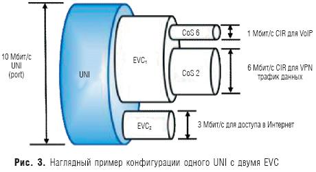
The first virtual connection EVC1 is used to exchange voice traffic and application data. VoIP traffic and VPN data traffic are known to require different quality of service. Therefore, within one EVC, using service attributes, different service levels are set: for VoIP traffic, it is CoS 6 (maximum quality), for VPN data traffic, it is CoS 2 (quality close to the minimum). In addition to classes of service for VoIP and data traffic, different values of the guaranteed bandwidth are also set: for VoIP - 1 Mbps, for data traffic - 6 Mbps.
The second channel EVC2 is designed to connect the user's site with the access point (POP) of the Internet service operator. For this, the guaranteed quality parameters of EVC are not configured, and if other types of traffic are not transmitted, then Internet traffic will occupy the entire channel width (10 Mbit / s). But with the advent of download in EVC1, the speed in the EVC2 channel will decrease.
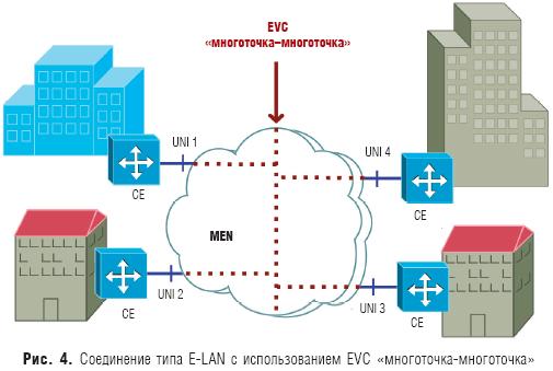
Multipoint-to-multipoint ( E - LAN)
Ethernet connection E - LAN provides multipoint connectivity. User data sent from a single UNI can be received by one or more UNIs connected to a multipoint virtual connection. When a new site is added, it connects to the same multipoint EVC, making it easy to set up hardware and activate services. From the user's point of view, E-LAN actually looks like a local Ethernet network (LAN) ( rice. 4).
The E-LAN connection can be used to provide a wide range of services. In the simplest case, this is data transmission with the highest possible performance, but without quality guarantees. In a more complex design, E-LAN allows you to set the quality of service parameters.
This connection also allows you to support multiplexing one or more EVCs into one UNI. For example, both E-LAN and E-Line services can be simultaneously configured on one of the UNIs. In this case, using multiplexing on one UNI, the E-LAN service can be used to connect the user's sites, and E-Line - to connect to the Internet.
Difference between E-LAN connection and typical network topology Frame Relay hub and spoke is obvious. Frame Relay PVC are point-to-point connections and multipoint services are organized over multiple point-to-point PVCs.
E-Tree Connection
The E-Tree connection type is a virtual root-to-multipoint Ethernet connection between multiple UNIs ( rice. 5).
In the simplest implementation, this is one root (root UNI) and many so-called leaves (UNI-leaf) - by analogy with the structure of a tree. Each UNI leaf can only communicate with the root UNI. A service Ethernet frame (frame) sent from one UNI leaf to another UNI leaf will not be delivered. This type of connection can be used to implement a mass Internet access service or video over IP. This may apply one or more types of class of service (CoS).
In a more complex implementation, an E-Tree can have two or more roots (root UNIs). In this scenario, each leaf can exchange data with only one root, but the roots can exchange data with each other. This scheme implements redundant root access for reliability and flexibility.
Multiplexing can also be used for the E-Tree connection (multiple EVCs in one UNI). For example, nothing prevents on one UNI from combining a root-to-multipoint EVC together with a point-to-point EVC. In this scenario, a root-to-multipoint EVC can be used to serve specific application traffic by providing access to reserved resources (different roots), and a separate point-to-point EVC can be used to communicate between user sites.
Practice of using Ethernet connections
Let's consider the features of the most popular Ethernet services demanded by telecom operators.
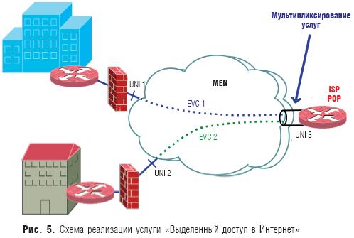
Dedicated Internet access. Because users are interested in high-speed Internet connectivity, EVC point-to-point service ideally connects the user's site to the nearest point of presence (POP) of an Internet operator (ISP).
In the simplest scenario, a user's site might use untagged service frames. To connect to two or more operators, the user can use the Boarder Gateway Protocol (BGP). In this case, he must use a separate E-Line for each ISP.
The operator is recommended to use multiplexing of user services on one high-speed Ethernet UNI. For example, as shown in fig. 5, the operator can have a 1 Gbps UNI connection (UNI 3), and users can have UNI 1 and UNI 2 at 100 Mbps each. In this example, service multiplexing is used only on the operator's side, since users have a dedicated Ethernet connection to the Internet operator's point of presence.
Expansion of the LAN.Imagine that there is a consumer with many sites in one metro area who wants to connect them together at high speed, so that these sites look like one LAN with performance equivalent to an office LAN, while providing access to servers and data warehouses of the enterprise.
This is the most common example of a LAN extension service that connects LAN users without any intermediate routing between different UNIs (sites). In some cases, this is simpler and cheaper than routing, but scalability issues can arise for very large networks.
The LAN Expansion service assumes a switch-to-switch connection, and this requires more transparency from the operator's network than for the Dedicated Internet access service. For example, a user might want to use Spanning Tree Protocol (STP) across connected sites while requiring the operator to support Bridge Packet Data Unit (BPDU) tunnels. If the user's network uses VLANs that separate traffic from different departments, the user will also need to render VLANs across multiple sites, requiring support for migrating custom CE-VLAN tags over MEN connections.
An example of the implementation of the LAN Expansion service with the participation of four sites connected via MEN is shown in Fig. 4. Three separate user VLANs are present in only some, but not all, sites. This example demonstrates the basic function of traffic routing services between sites. Each interface must support storing the CE-VLAN ID and CE-VLAN CoS — in other words, the custom VLAN tag and 802.1p bit must not be mapped to MEN. In this case, the MEN looks like a single Ethernet segment in which each site can be a member of any VLAN. The advantage of this approach is that the user can configure CE-VLAN across all four sites without any coordination or operator interaction.
Intranet / extranet L2 VPN. Ethernet services can be a good option for routed intranet connections between remote sites and extranet connections for vendors, customers, and other business partners of the user's organization.
Television broadcasting (Video Broadcast). On the basis of E-Tree connections, television broadcasting can be organized - the transmission of video signals from a source to a multitude of consumers. In this scenario, from the site where the video head-end is located, through the UNI, which is the root, many EVCs are organized to the UNI of users (leaves). The connection can support multiple broadcast channels that deliver data from root to leaf, in other words, from the video head-end to users, in one direction. A scenario like this has the same scalability benefits as an E-Line connection.
The user can also receive certain channels to which he is subscribed. Signaling, responsible for identifying these channels for each individual user, is implemented through a standard multicast protocol, for example IGMP v3.
In the case where redundancy is needed, two root UNIs can be used, the interaction between which takes place using redundancy protocols, which are responsible for ensuring that data is transferred from only one root through the EVC to users.
Metro Ethernet as the basis for telecom operator services
By using Metro Ethernet connections as the basis for operator services, a significant set of existing applications can be supported more easily, efficiently and cost effectively than other network capabilities and standards.
Using a typical Ethernet interface, the user can establish a secure dedicated virtual Ethernet connection over the metro network or over the WAN, consolidate their sites, connect business partners, suppliers or customers, and provide an Internet connection.
In addition, many services built on Metro Ethernet connections have unique flexibility in managing guaranteed bandwidth. This allows the user not to think about how he can increase the bandwidth between his sites, if required by applications.
The key to the present and future development of services based on Metro Ethernet is their simplicity, relative cheapness and availability, provided that the operator implements an appropriate architectural solution.
Based on materials from Priokom
preparedVladimir SKLYAR,
A little about cablesAny wired network starts with cables and Ethernet is no different. Therefore, the consideration of connecting to Ethernet networks should start with cables.
Coaxial cable was originally used as a cable in Ethernet networks in two variations: "thin" and "thick". Its structure is somewhat reminiscent of a cable from a television antenna. The maximum distance was 185 M (for "thin") and 500 M (for "thick"). Maximum speed- 10 Mbps in half duplex mode. Now twisted pair has replaced coaxial cable. It provides speeds from 10 Mbps to 1000 Mbps. An important advantage is considered to be support for full-duplex mode, when data can be transmitted in two directions at the same time. In this case, the problem of collisions disappears.
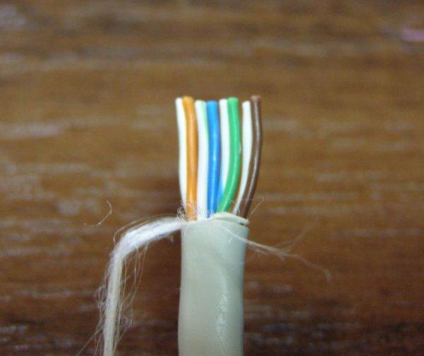
In the same material, only twisted pair connections will be considered. It consists of a sheath and four pairs of wires, which are twisted in a certain way. The twist step is different for each pair. This is done in order to minimize signal attenuation in the cable. The maximum distance is 100 M (although in practice it is more)
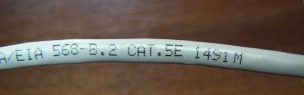
There are several categories of such cables: CAT-3 (now almost not used), CAT-5, CAT-5E (with support for speeds of 1000 Mbit / s), CAT-6, etc. The differences come down mainly to the maximum bandwidth. The most common and cheapest cables are CAT-5E.
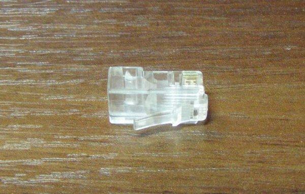
The connector for connecting to Ethernet networks is called RJ-45, is somewhat reminiscent of a connector for connecting phones. That one is called RJ-11
There are 3 types of cables:
- STP(shielded cable, each of 4 pairs has its own foil shield + all 4 pairs are wrapped in foil)
- ScTP(shielded cable, all 4 pairs are wrapped in foil). It looks something like this:
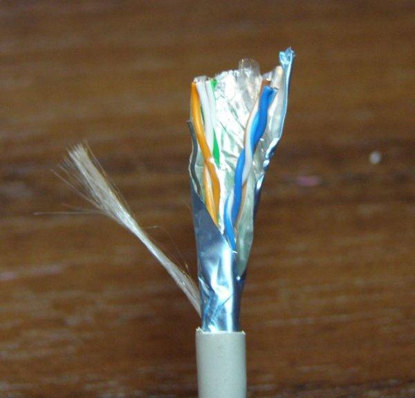
- UTP(unshielded). This cable looks something like this:

Note: The use of shielded cables is only appropriate when the cable shield is grounded. If it is not grounded, then the effect of the screen tends to zero!
Ethernet technology has two main types of cables:
Direct (used to connect a laptop / PC to switches (switches), hubs (hubs), routers to switches and hubs)
Crossover (used to connect laptop / PC to laptop / PC, laptop / PC to router, router to routers, switches to switches or hubs)
These cables differ in the way they are connected to the connector. Let's consider this issue in more detail:
There are two main layouts of conductors in a connector: TIA / EIA 568A and 568B... The cable has 4 pairs of different colors: orange, green, blue and brown.
Here is the layout of the conductors in the connector for the standard 568A:
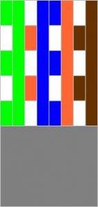
And here is the diagram for 568B:


This is how the cables look already with connectors. Left 568A, and on the right 568B:

So that's it. If at one end of the cable the conductors are arranged in one pattern, and at the other end along the other, then this will be a crossover cable, which is mainly used to connect a laptop / PC to a laptop or PC. In other words, if at one end of the cable the conductors are located according to the 568A standard, and on the other - according to the 568V standard, then this will be a crossover.
If, on both ends, the conductors are placed the same - either according to the 568A scheme, or according to the 568B scheme, then this will be a straight cable, which is used mainly to connect a laptop / PC to switches (switches)
Crimping cable
Note: "cable crimping" is a process when connectors are attached to the ends of the cable to connect to the network card
The cable can be crimped in some computer stores for a small fee. Typically, cables can be crimped where they are sold. You just need to clarify which cable you need: "straight" or "crossover". What is the difference between them described above
I will describe the process of crimping the cable. For this we need:
The cable itself (0.1-0.3 $ / meter. We buy with a margin)
Connectors RJ-45(sold for about $ 0.05-0.15 / piece. We buy with a margin) They look something like this:
Caps (if needed). They look like this:

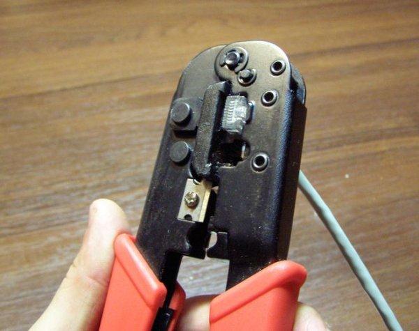
Crimping pliers (cost about $ 10-20)

When you have all you need, you can start. First of all, we remove some of the external insulation. You need to cut off about 12 mm. Some pliers have a special knife for this. The cable is clamped and rolled:
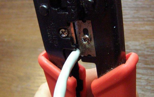
After the end of the procedure, we get something like this:

Now we have before us the most "interesting" part - to arrange the conductors in the correct order according to the 568A or 568B diagrams. It is not recommended to unwind the conductors strongly. This can lead to increased cable losses. At short distances, this can be ignored. To make it easier to place the conductors, you can use the connector itself. There are grooves there to help straighten and position the wires.
When the conductors are located as needed, we cut their edges so that they are approximately the same length. For the layout 568V:
Once the conductors have been positioned and trimmed, you can put on the plug itself. It is worth making sure that all conductors fall into their "own" grooves and that they are fully pushed in:
When the cable is inserted into the connector, it can be crimped. For this we need special pliers:
That's all. Now you can connect the cable. If everything is done correctly, the cable is not interrupted anywhere, the connectors are properly secured and the network cards are working, then the should light up green light on the network card:
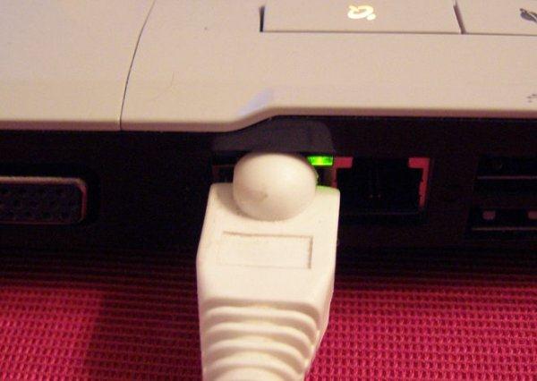

When you figured out the connection, you can go to the interface settings.
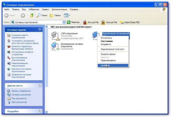
Setting up a connection in Windows XP
We go to the page Network connections LAN connection(the name can be very different, it is important that that connection uses your Ethernet card) and click on Properties
In the connection properties, select Internet Protocol (TCP / IP) and click on Properties:
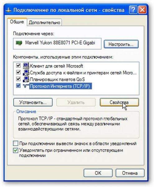
On this page, specify the IP address, subnet mask, DNS server and gateway addresses. If a PC or laptop is planned to be used as a gateway that is connected to the Internet and through it other PCs / laptops in the network must go to the Internet - indicate the IP address 192.168.0.1

In order for other computers or laptops to have access to the Internet using one connection, you need to go to the properties of this connection on the computer through which you want to organize access:
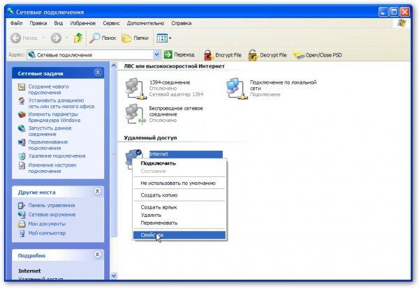
Then go to the tab Additionally and put a tick next to Allow other network users ...

That's all. Now users of the local network to which this computer is connected will be able to use the Internet. To do this, in their connection settings, you need to register in the fields Gateway and DNS server address 192.168.0.1 ... IP addresses can be any from the range 192.168.0.2 ... 192.168.0.254
Options:

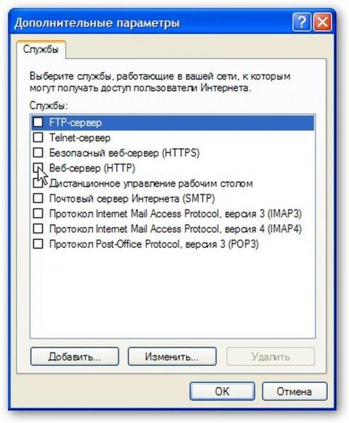
On the page that appears, indicate which servers you need access from the Internet:
Note: this feature is necessary so that users of the World Wide Web can access a specific server on the internal local network. Take, for example, the case where there is an HTTP server on the internal LAN. Microsoft's implementation of Internet Sharing (ICS) is very similar in principle to NAT. If this option is not enabled, then when a request is received on port 80, which corresponds to the HTTP protocol, the computer that is connected to the Internet will honestly "answer" that there is no such server, since it is not running on that computer. If you enable this option, then requests for port 80 will be automatically transmitted to the selected computer in the internal LAN.
On this page, we indicate where to redirect requests from such and such a port:
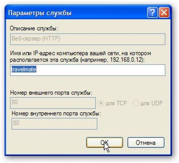
Now Internet users will be able to access your internal HTTP server
Connection setup in Windows Vista / 7
First we run Network and Sharing Center... Click on the left Network connection management:
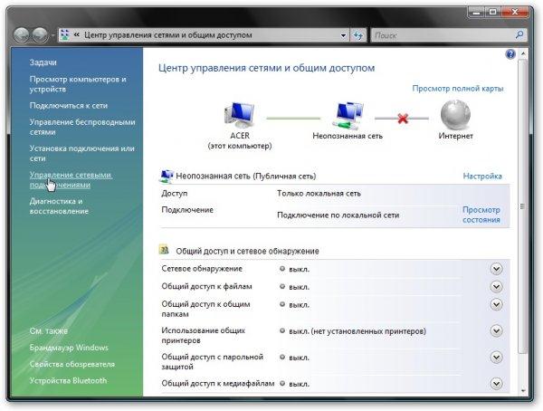
We go to the page Network connections, click right click mice on LAN connection(the name may be different, you need that connection to use your Ethernet card) and click on Properties

In the connection properties, select from the list Internet Protocol (TCP / IP) and click on Properties:

On this page, specify the IP address, subnet mask, DNS server and gateway addresses.
If a PC or laptop is planned to be used as a gateway that is connected to the Internet and through it other PCs / laptops in the network must access the Internet - indicate the IP address 192.168.0.1 , if you just need to connect to the network - you can specify another IP

Click OK. If everything is correct, then Windows Vista will prompt you to select a network location. According to it, various security policies will be applied. For home network- select the appropriate item:

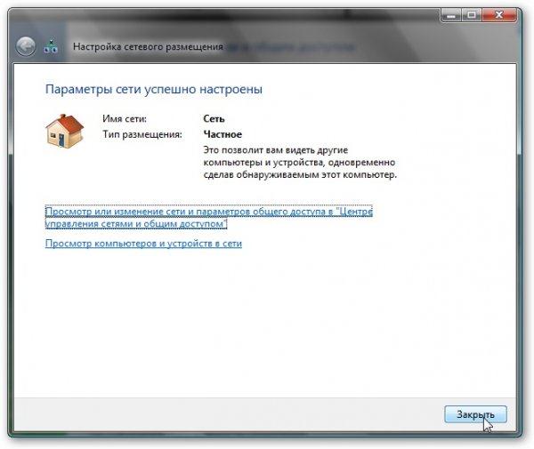
Here's the result:
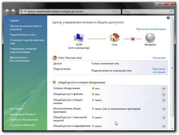
When the gateway (the computer through which the network is accessed, according to the settings it has IP 192.168.0.1) is turned on, then Internet access will appear for this laptop or PC.
Organization of Internet access for computers on the network through one connection:
In order for other computers or laptops in your network to have access to the Internet using one connection, you need to go to the Internet connection properties on the computer through which you want to organize access:

In the tab Access put a tick next to Allow other users ..:

That's all. It remains only to configure other computers on the network to work through this connection. To do this, in their connection settings, specify the IP address of this computer in the field Gateway and DNS server... All computers, of course, must be on the same network.
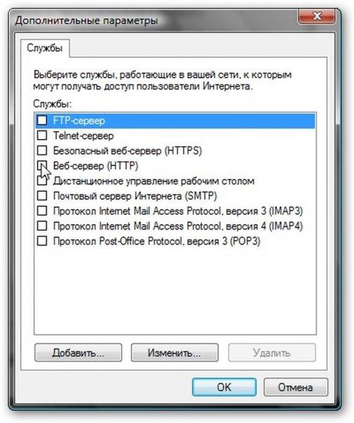
If you have servers on your network that you need to access from the Internet, then click on the button Setting ..., select the required servers (or add our own):
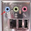 How do I enable line-in?
 Recovering deleted files from a USB flash drive
 Installing windows 8 64 bit