Types of pci e slots. Why do you need a pci-e pci adapter - detailed guide. PCI-E bus formats
PCI - Express (PCIe,PCI -E)- serial, universal bus first published July 22, 2002 of the year.
Is an general, unifying a bus for all nodes of the motherboard, in which all devices connected to it are adjacent. Came to replace the obsolete tire PCI and its variations AGP, due to the increased requirements for the bus bandwidth and the impossibility for reasonable means to improve the speed indicators of the latter.
The bus acts as switch by simply sending the signal from one point to another without changing it. This allows, without obvious loss of speed, with minimal changes and errors transmit and receive a signal.
Bus data goes simplex(full duplex), that is, simultaneously in both directions at the same speed, and signal along the lines, flows continuously, even when the device is turned off (like DC, or a bit signal of zeros).
Synchronization constructed by a redundant method. That is, instead of 8 bit information transmitted 10 bit, two of which are service (20% ) and in a certain sequence serve beacons for synchronization clock generators or identifying errors... Therefore, the declared speed for one line in 2.5 Gbps, is actually equal to approximately 2.0 Gbps real.
Nutrition each device on the bus, selected separately and regulated using technology ASPM (Active State Power Management). It allows, when the device is idle (without signaling) underestimate its clock generator and switch the bus to the mode reduced power consumption... If there is no signal for a few microseconds, the device considered inactive and is transferred to the mode expectations(time depends on the type of device).
Speed characteristics in two directions PCI - Express 1.0 :*
1 x PCI —E ~ 500 Mbps
4x PCI —E ~ 2 Gbps
8 x PCI —E ~ 4 Gbps
16x PCI —E ~ 8 Gbps
32x PCI-E ~ 16 GB
* Data transfer speed in one direction is 2 times lower than these indicators
January 15, 2007 PCI —SIG released an updated specification called PCI-Express 2.0
The main improvement was in 2 times faster speed data transmission ( 5.0 GHz, against 2.5GHz v old version). Improvement has also undergone point-to-point data transfer protocol(point-to-point), revised software component and added system software monitoring behind the bus speed. At the same time, compatibility with protocol versions PCI -E 1.x
V new version standard ( PCI -Express 3.0 ), the main innovation will be modified coding system and synchronization... Instead of 10 bit systems ( 8 bit information, 2 bits service) will apply 130 bit (128 bit information, 2 bits service). This will reduce losses in speed from 20% to ~ 1.5%... Will also be redesigned synchronization algorithm transmitter and receiver, improved PLL(phase-locked loop).Transmission speed increase presumably 2 times(in comparison with PCI -E 2.0), wherein compatibility will remain with past versions PCI —Express.
Features and Benefits
NVIDIA® Unified Architecture
The fully unified graphics core dynamically distributes geometry, vertex, physics, or pixel shading work for superior graphics performance.
NVIDIA CUDA ™ Parallel Computing Architecture 1
CUDA technology unleashes the power of the GPU cores and accelerates the most demanding system tasks like video transcoding, delivering incredible performance gains over traditional CPUs.
DirectCompute support
Full support for DirectCompute, Microsoft's GPU Computing API
OpenCL support
OpenCL support
Support Microsoft Windows 7
Windows 7 is the next generation operating system that will see significant improvements in the way it operating system to unleash the benefits of GPUs for an unprecedented visual experience. By leveraging these advantages for graphics and computing, Windows 7 will make modern PCs not only more interactive and attractive in terms of graphics, but also fully satisfy users' demands for speed and performance.
NVIDIA® GeForce® Unified Driver Architecture (UDA)
Offers a proven level of compatibility, reliability and stability with a wide range of games and applications. GeForce Drivers deliver an unprecedented user experience and support high performance and update capabilities throughout the life of your GeForce GPU.
GigaThread ™ technology
The massive multithreaded architecture supports thousands of independent parallel threads, delivering incredible computational power and advanced next-generation shader.
NVIDIA® Lumenex ™ engine
NVIDIA® Lumenex ™ engine
Technology 16
multiple smoothing
Floating point high dynamic range (HDR) bit lighting
Doubled the accuracy of the previous generation for incredibly realistic lighting effects, now with anti-aliasing support.
NVIDIA® PureVideo® HD Technology 2
It is a combination of high-definition video decoding acceleration and post-processing, delivering unprecedented image clarity, smooth video, correct colors and precise image scaling for movies and videos.
Hardware accelerated decoding
Provides ultra-smooth playback of H.264, VC-1, WMV, DivX, MPEG-2 and MPEG-4 HD and SD movies without the need for a dual or quad core CPU.
Dual-threaded hardware acceleration
Supports picture-in-picture mode for interactive viewing of Blu-ray and HD DVD movies.
Dynamic contrast enhancement and color stretching
Post-process and optimize HD movies scene by scene for amazing picture clarity.
Better Error Resilience
Correct errors and recover losses in broadcast content for crisp, high-quality playback.
Advanced space-time deinterlacing
Sharpens interlaced HD and SD content on progressive displays for crisp, clear images comparable to those of advanced home theater systems.
High quality scaling
Upscaling movies to HDTV. At the same time, the clarity and clarity of the image is maintained. Also downsampling of videos, including HD, while preserving details.
Reverse telecine (3: 2 & 2: 2 correction)
Recover original images from movies converted to videos (DVDs, 1080i HD content), more accurate video reproduction and superior picture quality.
Correction of unsuccessful editing
When editing video, adjustments made may disrupt the normal 3: 2 or 2: 2 scan. PureVideo technology uses advanced processing techniques to detect bad edits, restore original content, and render superior picture detail frame by frame for smooth, natural video.
Noise reduction
Improve video quality by removing unwanted artifacts.
Enhancing the edges of objects
Clearer images in videos by increasing contrast around lines and objects.
Dual-link HDCP 3 support
Complies with the output protection control (HDCP) and security specifications for Blu-ray format for playing protected video content on HDCP compliant monitors.
Dual Dual-link DVI support
Works with the industry's largest flat panel displays with the highest resolution (up to 2560x1600 pixels) and high-bandwidth digital content protection (HDCP) support.
HDMI 1.3a support
Fully integrated HDMI 1.3a support with xvYCC support, deep color and 7.1 surround sound
PCI Express 2.0 support
Built for new architecture PCI bus Express 2.0 for the fastest transfer speeds in the most bandwidth-hungry games and 3D applications with support backward compatibility with modern PCI Express motherboards.
Microsoft® DirectX® 10.1 support
DirectX 10.1 with Shader Model 4.1 support.
Optimization and support for OpenGL® 3.0
Ensures top-notch compatibility and performance for OpenGL applications.
Specification
| Supported displays: | |
| Maximum resolution of digital monitor | 2560x1600 |
| Max VGA Resolution | 2048x1536 |
| Standard monitor connectors | DVI, VGA, HDMI |
| Multiple monitor support | |
| HDCP | |
| HDMI | as a dummy plug (DVI-HDMI or DP-HDMI) |
| Audio input for HDMI | interior |
| Standard video card sizes: | |
| Height | 4.376 inches (111 mm) |
| Length | 6.6 inches (168mm) |
| Width | single slot |
| Temperature and power: | |
| Maximum GPU temperature (in C) | |
| Maximum graphics card power (W) | |
| Minimum system requirements on power supply (W) |
2.2.5 Hard disk.
Hard disk drive or HDD- an information storage device based on the principle of magnetic recording. It is the main storage of data in most computers.
Unlike a "floppy" disk (floppy disk), information in a hard disk drive is recorded on hard (aluminum, ceramic or glass) plates covered with a layer of ferromagnetic material, most often chromium dioxide. The HDD uses from one to several plates on one axis. The readheads in the operating mode do not touch the surface of the plates due to the interlayer of the incoming air flow formed at the surface during rapid rotation. The distance between the head and the disc is a few nanometers (in modern discs about 10 nm), and the absence of mechanical contact ensures a long service life of the device. In the absence of rotation of the disks, the heads are located at the spindle or outside the disk in a safe zone, where their abnormal contact with the surface of the disks is excluded.
Interfaces used: ATA (IDE and PATA), SATA, eSATA, SCSI, SAS, FireWire, USB, SDIO and Fiber Channel.
DEVICE
The hard disk consists of a containment area and an electronics unit (Fig. 14).
Containment area includes a body made of a durable alloy, the actual disks (plates) with a magnetic coating, a head unit with a positioning device, an electric spindle drive.
The head block is a set of spring steel levers (a pair for each disc). At one end, they are fixed on an axis near the edge of the disc. At the other ends (above the discs) heads are fixed.
Discs (plates) are usually made of a metal alloy. Both planes of the plates, like a tape recorder, are covered with the finest dust of a ferromagnet - oxides of iron, manganese and other metals.
The discs are rigidly fixed to the spindle. During operation, the spindle rotates at a speed of several thousand revolutions per minute (3600, 4200, 5400, 5900, 7200, 9600, 10,000, 15,000). At this speed, a powerful air stream is created near the surface of the plate, which lifts the heads and makes them float above the surface of the plate. The shape of the heads is calculated so as to provide the optimal distance from the plate during operation. Until the discs have accelerated to the speed required for the heads to take off, the parking device keeps the heads in the parking zone. This prevents damage to the heads and the working surface of the plates. Spindle motor hard disk three-phase, which ensures the stability of rotation of magnetic disks mounted on the axis (spindle) of the motor. The stator of the motor contains three windings, connected in a star with a tap in the middle, and the rotor is a permanent sectional magnet. Hydrodynamic bearings are used in the engine to ensure low runout at high rpm.
The head positioner consists of a fixed pair of strong neodymium permanent magnets and a coil on the moving head assembly
.Electronics unit... in modern hard drives The electronics unit usually contains: a control unit, read only memory (ROM), buffer memory, an interface unit and a digital signal processing unit.
The interface box connects the hard drive electronics to the rest of the system.
The control unit is a control system that receives electrical signals for positioning the heads, and generates control actions for a "voice coil" drive, switching information flows from various heads, controlling the operation of all other nodes (for example, controlling the spindle rotation speed), receiving and processing signals from device sensors (the sensor system may include a uniaxial accelerometer used as a shock sensor, a triaxial accelerometer used as a free fall sensor, a pressure sensor, an angular acceleration sensor, a temperature sensor).
The ROM block stores control programs for control units and digital signal processing, as well as service information of the hard drive.
The buffer memory smooths out the difference between the speeds of the interface part and the drive (high-speed static memory is used). Increasing the size of the buffer memory in some cases can increase the speed of the drive.
The digital signal processing unit cleans the read analog signal and decodes it (extracting digital information). Various methods are used for digital processing, for example, the PRML method (Partial Response Maximum Likelihood). The received signal is compared with samples. In this case, a sample is selected that is most similar in shape and time characteristics to the decoded signal. Figure 14.

HDD device diagram. (Fig. 14)
Since the motherboard supports Serial ATA, HDD ST3160316AS with a capacity of 160 GB, a spindle rotation speed of 7200 rpm, a memory buffer capacity of 8 MB. (Figure 15). The capacity of 160GB is sufficient for work in a training laboratory.


Figure 15 HDD ST3160316AS
2.2.6 Optical storage device.
Optical drive is an electrical device for reading and
you can record information from optical media (CD-ROM, DVD-ROM).
The following types of drives exist:
· CD-ROM drive (CD-drive);
· DVD-ROM drive (DVD drive);
· HD DVD drive;
· BD-ROM drive;
· GD-ROM drive;
The student workstations are not equipped with optical drives, and the NEC DV-5800D CD / DVD drive was chosen for the teachers.
2.2.7 Case and power supply
Power Supply(BP) - a device designed to generate the voltage required by the system from the voltage of the electrical network. Most often, power supplies convert an alternating current of a 220 V network with a frequency of 50 Hz (for Russia, in other countries, different levels and frequencies are used) into a given direct current.
The classic power supply is transformer power supply... In general, it consists of a step-down transformer or autotransformer, in which the primary winding is designed for the mains voltage. Then a rectifier is installed that converts alternating voltage into direct voltage (pulsating unidirectional). After the rectifier, a filter is installed to smooth out oscillations (pulsations). Usually it is just a large capacitor.
Also, the circuit can be equipped with filters for high-frequency interference, bursts, short-circuit protection, voltage and current stabilizers.
Switching power supplies are an inverter system. In switching power supplies, the AC input voltage is first rectified. Received constant pressure it is converted into rectangular pulses of increased frequency and a certain duty cycle, either supplied to the transformer (in the case of pulsed power supplies with galvanic isolation from the mains) or directly to the output low-pass filter (in pulsed power supplies without galvanic isolation).
Currently, there are mainly two standard enclosures in use. These are ATX and BTX, so they are the most promising today.
The main feature of the ATX standard (Fig. 17) is that the fan is located on the wall of the power supply case, which faces the inside of the computer, and the air flow is driven along the motherboard, coming from outside. The airflow in the ATX unit is directed to the components on the board that generate the most heat (processor, memory modules, and expansion cards).
All modern processors have an active heatsink, which is a small fan installed on the processor to cool it down. The ATX model power supply takes air from the outside and creates excess pressure in the case, while the pressure is reduced in the cases of other systems. Reverse airflow has significantly improved the cooling of the processor and other system components. With this air direction, the components inside system unit less susceptible to dust.

Figure 16. ATX case.
Along with ATX, there is the BTX standard (Fig. 18). Externally, the BTX motherboard looks almost like a mirror image of the ATX - boards, due to which all PCI and PCI Express cards, including graphics adapters, are installed chips upward, which in itself improves the cooling situation.
But an even more important advantage of BTX is a new processor cooling scheme: now it is located on the front edge of the board, and is turned at 45 ° towards it. When assembling a computer, not the usual cooling device is installed on the processor, but the so-called Thermal Module, consisting of a fan, a radiator and combining them into a single box. As a result, cold air is blown around the processor heatsink by the fan from the outside of the computer.
Turning the processor by 45 ° solves two problems at once: firstly, the resistance of the processor socket to the incoming air flow decreases; secondly, in front of the nest, on its sides, there are VRM elements, which, with this scheme, are also cooled directly by the flow of cold outside air.
Motherboard is located not at the bottom edge of the cooling module, but slightly higher, due to which part of the air flow passes under the board, primarily VRM transistors.

Figure 17. BTX Case.
Despite the fact that the BTX standard has its significant advantages, ATX standard housings have been chosen for the educational laboratory, since this standard has long established itself and is widespread in the computer components market.
The case was Pangu Simple S1602BS ATX MidiTower, Black-Silve With an additional clair installed (Fig. 18).

Figure 18. Pangu Simple S1602BS ATX MidiTower Case, Black-Silve
Classic ATX case with Pangu S380 power supply.
Distinctive feature Simple series computer cases are inexpensive.
The case is equipped with a power supply unit with sufficient power for office and home computer not high performance.
The Simple series is an excellent choice for low-cost computers equipped with a mid-range PCI-E graphics card.
The power supply is equipped with connectors additional food 8pin 12V and 6pin PCI-E for video card.
Case type - Middle Tower
Drive Bays:
5.25 "- 3 pcs.
5.25 ”(inner) - 1pc.
3.5 ”(external) - 1pc.
3.5 ”(inner) - 4 pcs.
Color - Black / Silver
Materials:
o metal (SGCC 0.45mm)
o high quality plastic
Motherboards - ATX / Micro-ATX
Power supply standard - ATX
I / O ...
2.2.8 Monitor
Monitor is a universal device for visual display of all types of information, consisting of a display and devices designed to display text, graphic and video information on the display.
Currently, there are mainly 2 types of monitors in use: CRT monitors and LCD monitors.
CRT monitors... The most important element of a monitor is a picture tube, also called a cathode ray tube. The CRT consists of a sealed glass tube with a vacuum inside. One of the ends of the tube is narrow and long - this is the neck, and the other - wide and rather flat - is the screen. On the front side, the inner part of the glass tube is coated with a phosphor.
Lcd monitor- a flat panel display based on liquid crystals, as well as a monitor based on such a display.
The image is formed using individual elements, as a rule, through a scanning system. A multicolor image is formed using RGB triads.
Each LCD pixel consists of a layer of molecules between two transparent electrodes, and two polarizing filters, the polarization planes of which are (as a rule) perpendicular. In the absence of liquid crystals, the light transmitted by the first filter is almost completely blocked by the second.
The most important characteristics LCD monitors:
Permission: Horizontal and vertical dimensions, expressed in pixels. Unlike CRT monitors, LCDs have one fixed resolution, the rest are achieved by interpolation.
Point size: the distance between the centers of adjacent pixels. Directly related to physical resolution.
Screen aspect ratio (aspect ratio): The ratio of width to height, for example: 5: 4, 4: 3, 5: 3, 8: 5, 16: 9, 16:10.
Visible diagonal: the size of the panel itself, measured diagonally. The area of displays also depends on the format: a monitor with a 4: 3 aspect ratio has a larger area than a 16: 9 aspect ratio with the same diagonal.
Contrast: the ratio of the brightness of the lightest point to the darkest point. Some monitors use an adaptive backlight level using additional lamps, the contrast figure given for them (the so-called dynamic) does not apply to a static image.
Brightness: The amount of light emitted from a display is usually measured in candelas per square meter.
Response time: The minimum time it takes for a pixel to change its brightness. Measurement methods are ambiguous.
Viewing angle: the angle at which the drop in contrast reaches the specified value, for different types matrices and different manufacturers is calculated differently, and often cannot be compared.
Matrix type: The technology behind the LCD.
Inputs: for example, DVI, D-Sub, HDMI, etc.
For computers in the educational laboratory, taking into account the color of the case of the system unit, the LG monitor was selected L1742SE-BF (Fig. 19).

Figure 19. LG Monitor L1742SE-BF .
· Monitor parameters:
· Colors used in decoration: Black;
· Diagonal: 17 ");
· LCD Matrix Dot: 0.294mm;
· LCD brightness: 250 cd / m2;
· Contrast LCD-matrix: 2000: 1 - static, 50,000: 1 (ACM -adaptive contrast management);
· Monitor screen surface: Matte;
· Response time: 5ms; LCD-matrix format: 5: 4;
· LCD-matrix resolution: 1280 x 1024;
· Viewing angle of LCD-matrix: 160 ° horizontally, 160 ° vertically with CR> 10: 1;
· Interface: VGA (15-pin D-sub connector),;
· Monitor power supply: Built-in; Power Consumption: 38.5W maximum, 27.3W in Energy Star, 1.5W in standby
· Dimensions (width x height x depth): 408 x 406.8 x 180.4 mm; Weight: 3.91 kg.
2.2.9 Input devices.
Input devices - devices for entering (entering) data into a computer during its operation. The main devices for inputting information from the user into the computer are the mouse and keyboard.
Keyboard... A standard computer keyboard, also called a PC / AT keyboard or AT keyboard, has 101 or 102 keys. The layout of the keys on the AT-keyboard obeys a single generally accepted scheme, designed based on the English alphabet.
According to their purpose, the keys on the keyboard are divided into six groups:
· functional;
· alphanumeric;
· cursor control;
· digital panel;
· specialized;
· modifiers.
Twelve function keys located in the topmost row of the keyboard. Below is the block alphanumeric keys... To the right of this block are the cursor keys, and to the right of the keyboard is the numeric keypad.
Many modern computer keyboards, in addition to the standard set of one hundred and four keys, are supplied with additional keys(usually of a different size and shape), which are designed to simplify control of some of the basic functions of the computer (mainly multimedia). Such keyboards are called "multimedia keyboards".
Mouse perceives its movement in the working plane (usually on a section of the table surface) and transfers this information to the computer. The program running on the computer, in response to the movement of the mouse, performs an action on the screen that corresponds to the direction and distance of this movement.
· Displacement sensors:
· Direct drive;
· Ball drive;
· Optical mice first generation;
· Second generation optical mice;
· Laser mice;
· Induction mice;
· Gyroscopic mice.
Currently, the following interfaces are used to connect a keyboard and mouse: PS / 2 and USB.
For workstations in educational laboratories, a standard keyboard with additional multimedia capabilities was chosen Genius KB-200
Ergo (PS / 2, 104 keys, spill-resistant, wrist rest) (Fig. 20) and laser
Genius NetScroll 100 Optical USB mouse (USB, 3 keys, including a wheel-key) (Fig. 21).

Figure 20. Genius KB-200 Ergo Keyboard

Figure 21. Genius NetScroll 100 Optical USB Mouse
2.3.1 Printing devices.
a printer- a device for printing digital information onto solid media, usually paper. Refers to computer terminal devices.
The printing process is called printing, and the resulting document is a printout or hard copy.
Printers are inkjet, laser, matrix and sublimation, and in terms of print color - black and white (monochrome) and color.
Laser printers ... A static charge is evenly distributed over the surface of the photodrum by a corotron (soon a throne) of the charge, or by the charge shaft, a static charge is evenly distributed, after which the charge is removed by the LED laser (or LED ruler) on the photodrum, thereby placing a latent image on the surface of the drum. Next, toner is applied to the drum unit. Toner is attracted to the discharged areas of the drum surface, which retains the latent image. The drum is then rolled over the paper and the toner is transferred to the paper by a transfer corotron or transfer roller. The paper then passes through the fuser to fix the toner, and the drum is cleaned of toner residues and discharged in the cleaning unit.
Inkjet printers... The principle of operation of inkjet printers is similar to dot matrix printers in that the image on the medium is formed from dots. But instead of heads with needles, inkjet printers use a matrix that prints with liquid dyes.
Sublimation printers... Dye-sublimation is the rapid heating of a dye when the liquid phase has passed. Steam is generated immediately from the solid colorant. The smaller the portion, the greater the photographic width (dynamic range) of color reproduction. The pigment of each of the primary colors, and there can be three or four of them, is on a separate (or on a common multilayer) thin lavsan tape. The final color is printed in several passes: each tape is sequentially pulled under a tightly pressed thermal head, which consists of many thermocouples. These latter, when heated, sublimate the dye. The points, due to the small distance between the head and the carrier, are stably positioned and are very small in size.
Dot Matrix Printers... The image is formed by the print head, which consists of a set of needles (needle matrix) driven by electromagnets. The head moves line by line along the sheet, with the needles striking the paper through the ink ribbon, forming a dot pattern.
2.3.2 Scanners.
Scanner- a device that, by analyzing an object (usually an image, text), creates a digital copy of the object's image. The process of making this copy is called scanning.
There are handheld, roll-to-roll, flatbed and projection scanners. A variety of projection scanners are slide scanners designed for scanning photographic films. In high-quality printing, drum scanners are used, in which a photomultiplier tube (PMT) is used as a photosensitive element.
The principle of operation of a single-pass flatbed scanner is that a scanning carriage with a light source moves along the scanned image located on a transparent fixed glass. The reflected light through the optical system of the scanner (consisting of a lens and mirrors or a prism) hits three parallel CCD photosensitive semiconductor elements, each of which receives information about the image components.
A multifunctional device (MFP) was chosen for the educational laboratory
Canon i-SENSYS MF4410(Fig. 22).
MFP advantages:
· Space saving;
· Price. MFP printer-copier-scanner is much cheaper than all these
devices purchased separately;
The ability to do the whole range of work on one universal
· Ease of service;

Figure 22. Canon i-SENSYS MFPMF4410.
Common parameters:
- Positioning Print documents
- Memory capacity (Standard) (MB) 64
- Printing type Laser
- Color Printing No
- Media types Glossy paper, matte paper, envelopes
- Maximum print size A4
- Print resolution 600 x 600
- Cartridge type 728
- Availability of duplex printing No
- Borderless Printing No
- Print speed Up to 23 ppm
- Direct printing from a digital camera
- Scanner type Flatbed
- Scan resolution 9600 x 9600
- Zoom ratio 25-400%
- Fax Features No
- Interface USB connection
- Wireless connection No
- Power consumption Max. 1220 Wt
- Reason for choosing Monochrome 5-line display, affordable price
3 Assembly technology, computer settings, software installation.
3.1 Calculation of the cooling system.
CPU cooling calculation
For stable operation of the processor, it is necessary that its operating temperature does not rise above a certain level, otherwise, during operation, malfunctions and freezes of the machine are possible. The maximum operating temperature of the processor cores is 72.6 ° C; for reliability, the allowable temperature is assumed to be 60 ° C. The optimum temperature inside the system unit is 35 ° C. It is necessary to find out if the chosen cooler is capable of providing effective cooling of the processor case. Fundamental technical characteristics a cooler is the thermal resistance relative to the surface of the processor crystal - a value that allows you to evaluate its effectiveness as a cooling device.
The thermal resistance of the processor is calculated as follows:
Rt = (Tc-Ta) / W, (3.1)
where Rt is the thermal resistance of the radiator, ° С / W;
Tc is the processor temperature that must be reached by applying
cooler, ° С;
Ta is the temperature inside the computer case, ° С;
W is the thermal power dissipated by the processor, W.
CPU Intel Core The i3-560 dissipates 73W. Then the thermal resistance of the radiator will be equal to:
Rt = (60-35) / 73 = 0.34 ° C / W
The obtained value for the thermal resistance of the color includes the thermal resistance of the thermal interface. For thin layers (0.05 mm and less), such as thermal paste, the thermal resistance is in the order of 0.08 - 0.15 ° C / W. Therefore, to ensure a total thermal resistance of 0.15 ° C / W in the case of using high-quality thermal paste, the thermal resistance of the cooler should not exceed:
Rt = 0.34-0.08 = 0.26 ° C / W (3.2)
In the case of using a cooler supplied in a package with a processor (Fig. 17), the thermal resistance of which is 41 ° C / W, the maximum temperature of the processor will be equal to:
Tc = W * (Rt + 0.08) + Ta = 73 * (0.41 + 0.08) + 35 = 53.1 ° C (3.3)
Taking into account that the maximum core temperature of this processor is 72.6 ° C, this cooler was chosen.
CALCULATION OF CASE COOLING
Q = 1.76 * P / (Ta-T0) (3.4)
where P is the total thermal power of the computer system;
Ta is the temperature inside the system case;
That is the temperature "at the inlet" of the case (temperature in the room);
Q - performance (consumption) of the case cooling system.
The table shows the thermal power of the components.
Table 3 Thermal power of the component parts.
The temperature outside the case is 25 ° C, the desired temperature inside the case is 35 °. Then the fan performance should be equal to
formula (3.4):
Q = 1.76 * 208 / (35-25) = 37 CFM
The actual performance of the fan under specific operating conditions depends on the system impedance, which is expressed as:
P = k * Qn (3.5)
where k is a system constant,
Q - fan performance,
n - turbulent factor (1<= n <=2, n = 1 при ламинарном режиме течения потока, п = 2 при турбулентном течении потока),
P is the system impedance.
Table 4 Approximate values of the swap constant k.

MRZ - a small degree of filling of the case (occupied AGP slot, 1 PC slot !, 1 compartment for
devices 5.25 ”. 2 compartments for 3.5 ”devices).
CVD - average degree of filling of the case (occupied by AGP slot, 2-3 PCI slots or other buses,
2-3 5.25 "device bays, 2 3.5" device bays).
ВСЗ - high degree of filling of the case (AGP slot occupied, at least 4-5 PCI slots or
other buses, 3-4 5.25 "device bays, all available 3.5" device bays).
The value of this constant can be varied within ± 5% if the displacement of your case is slightly more or slightly less than the reference values.
Dimensional system constant is selected based on the total volume of the enclosure< 40л и малой степени заполнения корпуса (1 слот PCI-E, 1 слот PCI, 1 отсек для устройств 5.25", 2 отсека для устройств 3.5"). Требуемое значение = 0,06
The power supply unit of the case is standard, the fan works for blowing, which means that the flow is laminar. Turbulence Factor = 1. Since the chassis power supply has a standard 2500 RPM fan, its capacity is assumed to be 30 CFM. Then the system impedance is equal by formula (3.5):
P = 0.06 * 30 = 1.8 mtH2O
- Hello! Please explain the difference in bandwidth between PCI Express 3.0 x16 and PCI Express 2.0 x16. Now there are still on sale motherboards with the PCI Express 2.0 x16 interface. I'm with I will greatly lose in performance if I install a new video interface cardPCI Express 3.0 to a computer with a motherboard with only a slotPCI-E 2.0? I think that I will lose, because the totalbaud rate PCI Express 2.0 equals - 16 GB / s, and the totalthe data transfer rate of PCI Express 3.0 is twice as high - 32 GB / s
- Hey! I have a computer with a powerful but not new Intel Core i7 2700K processor and a motherboard that has a PCI Express 2.0 slot. Tell me, if I buy a new PCI Express 3.0 video card, this video card will work twice as slow as if I had a motherboard with a connector PCI Express 3.0? So it's time for me to change my computer?
- Please answer this question. My motherboard has two connectors: PCI Express 3.0 and PCI Express 2.0, but in the slot PCI Express 3.0 new graphics card PCI Express 3.0 does not climb, the radiator of the south bridge interferes. If I install a graphics cardPCI-E 3.0 to slot PCI-E 2.0, will my video card perform worse than if it were installed in a PCI Express 3.0 slot?
- Hello, I want to buy a little used motherboard from a friend for two thousand rubles. Three years ago he bought it for 7000 rubles, but I am confused by the fact that it has a slot for an interface video card PCI-E 2.0, and I have a video cardPCI-E 3.0. Will my graphics card on this motherboard run at full capacity or not?
Bandwidth Difference Between PCI Express 3.0 x16 and PCI Express 2.0 x16
Hello friends! Today on sale you can find motherboards with a connector for installing PCI Express 2.0 x16 video cards, and PCI Express 3.0 x16. The same can be said about graphic adapters, there are video cards on sale with an interface PCI-E 3.0 as well as PCI-E 2.0. If you look at the official specifications of the PCI Express 3.0 x16 and PCI Express 2.0 x16 interfaces, you will find out that the total data transfer rate for PCI Express 2.0 is- 16 GB / s, while PCI Express 3.0, it is twice as large -32 GB / s I will not delve into the jungle of the specifics of these interfaces and just tell you that there is such a big difference inthe data transfer rate is visible only in theory, in practice it is very small.If you read articles on this topic on the Internet, thenyou will conclude that modern PCI Express 3.0 graphics cards operate at the same speed in PCI Express 3.0 x16 and PCI Express 2.0 x16 slots and difference in throughputbetween PCI-E 3.0 x16 and PCI-E 2.0 x16 is only 1-2% loss of graphics card performance. That is, it doesn't matter which slot you install the video card into, PCI-E 3.0 or PCI-E 2.0, everything will work the same.
But unfortunately, all these articles were written in 2013 and 2014, and at that time there were no games like Far Cry Primal, Battlefield 1 and other new products that appeared in 2016. Also in 2016 was released family of NVIDIA 10-series GPUs, for example, GeForce GTX 1050 and GeForce GTX 1050 Ti graphics cards, and even GTX 1060. My experiments with new games and new video cards have shown that the advantage of the PCI-E 3.0 interface overPCI-E 2.0 is no longer 1-2%, but on average 6-7%. What is interesting if the video card is lower in class than GeForce GTX 1050 , then the percentage is less (2-3%) , and if on the contrary, then more - 9-13%.
So, in my experiment I used a video card GeForce GTX 1050 PCI-E 3.0 interface and motherboard with connectors PCI Express 3.0 x16 and PCI Express 2.0 x16.
H Graphics settings in games are maximum everywhere.
- FAR CRY PRIMAL game. Interface PCI-E 3.0 has shown an advantage over PCI-E 2.0 since always higher by 4-5 frames, which in percentage terms is approximately 4 % %.
- Battlefield 1 game. The gap between PCI-E 3.0 and PCI-E 2.0 was 8-10 frames , which is in a percentage ratio of about 9%.
- Rise of the Tomb Raider. Advantage of PCI-E 3.0 averages 9- 10 fps or 9%.
- The witcher. The advantage of PCI-E 3.0 was 3%.
- Grand Theft Auto V. The advantage of PCI-E 3.0 is 5 fps or 5%.
That is, the difference in bandwidth between the PCI-E 3.0 x16 and PCI-E 2.0 x16 interface is still not in favor PCI-E 2.0. Therefore, I would not buy a motherboard with one PCI-E 2.0 slot at the moment.
A friend of mine bought a used motherboard for three thousand rubles. Yes, once it was heaped up and cost about ten thousand rubles, it has a lot of connectors SATA III and USB 3.0, also 8 slots for RAM, it supports RAID technology, etc., but it is built on an outdated chipset and a slot for a video card on it PCI Express 2.0! My opinion, it would be better to buy. Why?
It may well happen that in a year or two, the latest video cards will only work in the slot PCI Express 3.0 x16 , and on your motherboard there will be an obsolete connector that is no longer used by manufacturers PCI Express 2.0 x16 ... You buy a new video card, and it will refuse to work in the old connector. Personally, I have already come across many times that the video card PCI-E 3.0 did not start on the mat. board with connector PCI-E 2.0, and even updating the BIOS of the motherboard did not help.I also dealt with video cardsPCI-E 2.0 x16 that refused to work on older motherboards with an interface PCI-E 1.0 x16, although everywhere they write about backward compatibility.Cases when the PCI Express 3.0 x16 video card did not start on motherboards withPCI Express 1.0 x16, even more.
Well, do not forget about the appearance this year of the interface. PCI Express 4.0. In this case, PCI Express 3.0 will be outdated.
 The PCI Express serial bus, developed by Intel and its partners, is intended to replace the PCI parallel bus and its extended and specialized AGP variant. Despite the similar names, PCI and PCI Express buses have little in common. The parallel data transfer protocol used by PCI imposes restrictions on the bandwidth and frequency of the bus; The serial data transfer used in PCI Express provides scalability (the specifications describe PCI Express implementations 1x, 2x, 4x, 8x, 16x, and 32x). At the moment, the version of the tire with an index 3.0 is relevant.
PCI-E 3.0
In November 2010, PCI-SIG, the PCI Express technology standardization organization, announced the adoption of the PCIe Base 3.0 specification.
The key difference from the previous two PCIe versions can be considered the changed coding scheme - now instead of 8 bits of useful information out of 10 bits transmitted (8b / 10b), 128 bits of useful information out of 130 bits sent can be transmitted over the bus, i.e. the payload ratio is almost 100%. In addition, the data transfer rate has increased to 8 GT / s. Recall that this value for PCIe 1.x was 2.5 GT / s, and for PCIe 2.x it was 5 GT / s.
All of the above changes resulted in a doubling of the bus bandwidth compared to the PCI-E 2.x bus. This means that the total bandwidth of the PCIe 3.0 bus in a 16x configuration will reach 32 Gb / s. The first processors to feature a PCIe 3.0 controller were Intel processors based on the Ivy Bridge microarchitecture.
Despite the more than three times the bandwidth of PCI-E 3.0 compared to PCI-E 1.1, the performance of the same video cards when using different interfaces does not differ much. The table below shows the benchmark results of the GeForce GTX 980 in various tests. The measurements were carried out with the same graphics settings, in the same configuration. The PCI-E bus version was changed in the BIOS settings.
PCI Express 3.0 is still backward compatible with previous PCIe versions.
PCI-E 2.0
In 2007, a new specification of the PCI Express bus - 2.0 was adopted, the main difference of which is the doubled bandwidth of each transmission line in each direction, i.e. in the case of the most popular PCI-E 16x version used in video cards, the bandwidth is 8Gb / s in each direction. The first chipset to support PCI-E 2.0 was Intel X38.
PCI-E 2.0 is fully backward compatible with PCI-E 1.0, i.e. all existing devices with PCI-E 1.0 interface can work in PCI-E 2.0 slots and vice versa.
PCI-E 1.1
The first version of the PCI Express interface, which appeared in 2002. Provided a throughput of 500 MB / s per line.
Comparison of the speed of different PCI-E generations
The PCI bus runs at 33 or 66 MHz and provides 133 or 266 MB / s bandwidth, but this bandwidth is shared among all PCI devices. The frequency at which the PCI Express 1.1 bus operates is 2.5 GHz, which gives a bandwidth of 2500 MHz / 10 * 8 = 250 * 8 Mbit / s = 250 Mb / s information) for each PCI Express 1.1 x1 device in one direction. If there are several lines to calculate the throughput, the value of 250 Mb / s must be multiplied by the number of lines and by 2, since PCI Express is a bi-directional bus.
| PCI Express 1.1 Lines | Throughput in one direction | Total throughput |
| 1 | 250 MB / sec | 500 MB / sec |
| 2 | 500 Mb / s | 1 GB / sec |
| 4 | 1 GB / sec | 2 GB / sec |
| 8 | 2 GB / sec | 4 GB / sec |
| 16 | 4 GB / sec | 8 GB / sec |
| 32 | 8 GB / sec | 16 GB / sec |
Note! You should not try to install a PCI Express card in a PCI slot, and conversely, PCI cards do not fit into a PCI Express slot. However, a PCI Express 1x card, for example, can be installed and will most likely function normally in a PCI Express 8x or 16x slot, but not vice versa: a PCI Express 16x card will not fit into a PCI Express 1x slot.
When changing only one video card, be sure to take into account that new models may simply not fit your motherboard, since there are not only several different types of expansion slots, but also several different versions of them (as applied to both AGP and PCI Express). If you are unsure of your knowledge of this topic, please read the section carefully.
As we have already noted above, the video card is inserted into a special expansion slot on the computer's motherboard, through this slot the video chip exchanges information with the central processor of the system. Motherboards often have one or two different types of expansion slots, differing in bandwidth, power settings, and other characteristics, and not all of them are suitable for installing video cards. It is important to know the connectors available in the system and buy only the video card that matches them. Different expansion connectors are physically and logically incompatible, and a video card designed for one type will not fit into another and will not work.
Fortunately, not only ISA and VESA Local Bus expansion slots (which are of interest only to future archaeologists) and their corresponding video cards have fallen into oblivion over the past time, but video cards for PCI slots have also practically disappeared, and all AGP models are hopelessly outdated. And all modern GPUs use only one type of interface - PCI Express. Previously, the AGP standard was widespread, these interfaces differ significantly from each other, including the bandwidth, provided by the possibilities for powering the video card, as well as other less important characteristics.
Only a very small part of modern motherboards do not have PCI Express slots, and if your system is so old that it uses an AGP video card, then you will not be able to upgrade it - you need to change the entire system. Let's take a closer look at these interfaces; these are the slots you need to look for on your motherboards. See photos and compare.
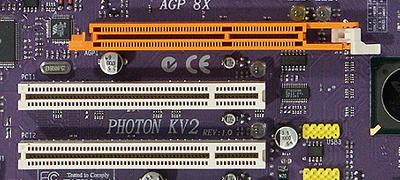
AGP (Accelerated Graphics Port or Advanced Graphics Port) is a high-speed interface based on the PCI specification, but designed specifically for connecting video cards and motherboards. Although the AGP bus is better suited for video adapters than PCI (not Express!), It provides a direct connection between the central processor and the video chip, as well as some other features that increase performance in some cases, for example, GART - the ability to read textures directly from RAM without copying them into video memory; higher clock frequency, simplified data transfer protocols, etc., but this type of slots is hopelessly outdated and new products with it have not been released for a long time.
But still, for the sake of order, we will mention this type as well. AGP specifications appeared in 1997, then Intel released the first version of the description, which included two speeds: 1x and 2x. In the second version (2.0) AGP 4x appeared, and in 3.0 - 8x. Let's consider all the options in more detail:
AGP 1x is a 32-bit channel operating at 66 MHz with a bandwidth of 266 MB / s, which is twice the PCI bandwidth (133 MB / s, 33 MHz and 32 bits).
AGP 2x is a 32-bit channel operating with twice the bandwidth of 533 MB / s at the same frequency of 66 MHz due to data transfer on two edges, similar to DDR memory (only for the direction "to the video card").
AGP 4x is the same 32-bit channel operating at 66 MHz, but as a result of further tweaks, a quadruple "effective" frequency of 266 MHz was achieved, with a maximum bandwidth of more than 1 GB / s.
AGP 8x - additional changes in this modification made it possible to get the bandwidth up to 2.1 GB / s.
AGP video cards and corresponding slots on motherboards are compatible within certain limits. Graphics cards rated for 1.5V do not work in 3.3V slots and vice versa. However, there are also universal connectors that support both types of boards. Video cards designed for a morally and physically outdated AGP slot have not been considered for a long time, so to learn about old AGP systems, it would be better to read the article:
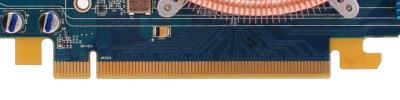

PCI Express (PCIe or PCI-E, not to be confused with PCI-X), formerly known as Arapahoe or 3GIO, differs from PCI and AGP in that it is a serial rather than parallel interface, which reduces the number of pins and increases bandwidth. PCIe is just one example of the shift from parallel to serial buses, other examples of this movement are HyperTransport, Serial ATA, USB and FireWire. An important advantage of PCI Express is that it allows multiple single lanes to be stacked into a single lane to increase bandwidth. The multichannel sequential design increases flexibility, slower devices can be assigned fewer lines with fewer pins, and faster ones more.
PCIe 1.0 transfers data at 250 MB / s per lane, nearly double the capacity of conventional PCI slots. The maximum number of lanes supported by PCI Express 1.0 slots is 32, which gives a bandwidth of up to 8 GB / s. And the PCIe slot with eight working lanes is roughly comparable in this parameter with the fastest AGP version - 8x. Which is even more impressive when you consider the possibility of simultaneous transmission in both directions at high speed. The most common PCI Express x1 slots provide bandwidth of one lane (250 MB / s) in each direction, and PCI Express x16, which is used for video cards and which combines 16 lanes, provides bandwidth up to 4 GB / s in each direction.
Despite the fact that the connection between two PCIe devices is sometimes assembled from several lines, all devices support a single line, at least, but can optionally work with a large number of them. Physically, PCIe expansion cards go in and work fine in any slots with equal or more lanes, so a PCI Express x1 card will work fine in x4 and x16 slots. Also, a physically larger slot can work with a logically fewer lines (for example, a seemingly ordinary x16 connector, but only 8 lines are routed). In any of the above options, PCIe itself will choose the highest possible mode, and it will work fine.
Most often, x16 connectors are used for video adapters, but there are boards with x1 connectors. Most motherboards with two PCI Express x16 slots operate in x8 mode to create SLI and CrossFire systems. Physically, other slot options such as x4 are not used for video cards. Let me remind you that all this applies only to the physical layer, there are also motherboards with physical PCI-E x16 connectors, but in reality with 8, 4 or even 1 channels. And any video cards designed for 16 channels will work in such slots, but with lower performance. By the way, the photo above shows the x16, x4 and x1 slots, and for comparison, PCI is also left (below).
Although the difference in games is not that big. For example, here is a review of two motherboards on our website, which examines the difference in the speed of 3D games on two motherboards, a pair of test video cards in which operate in 8-channel and 1-channel modes, respectively:
The comparison that interests us is at the end of the article, pay attention to the last two tables. As you can see, the difference at medium settings is quite small, but in heavy modes it starts to increase, and a big difference was noted in the case of a less powerful video card. Take note of this.
PCI Express differs not only in bandwidth, but also in new power consumption capabilities. This need arose because the AGP 8x slot (version 3.0) can only transfer no more than 40-plus watts in total, which was no longer enough for video cards of the then generations designed for AGP, on which one or two standard four-pin power connectors were installed. A PCI Express slot can carry up to 75W, and an additional 75W is received over a standard six-pin power connector (see the last section of this part). Recently, video cards with two such connectors have appeared, which in total gives up to 225 watts.
Subsequently, the PCI-SIG group, which develops the corresponding standards, presented the main PCI Express 2.0 specifications. The second version of PCIe doubles the standard bandwidth, from 2.5 Gbps to 5 Gbps, so the x16 connector can transfer data at speeds up to 8 Gbps in each direction. At the same time, PCIe 2.0 is compatible with PCIe 1.1, old expansion cards usually work fine in new motherboards.
The PCIe 2.0 specification supports both 2.5 Gb / s and 5 Gb / s transfer rates to ensure backward compatibility with existing PCIe 1.0 and 1.1 solutions. PCI Express 2.0 backward compatibility allows legacy 2.5 Gbps solutions in 5.0 Gbps slots, which would simply operate at a lower speed. And devices designed to specification version 2.0 can support speeds of 2.5 Gbps and / or 5 Gbps.
Although the main innovation in PCI Express 2.0 is the speed doubled to 5 Gbps, but this is not the only change, there are other modifications to increase flexibility, new mechanisms for programmatically controlling the connection speed, etc. We are most interested in the changes related to with power supply of devices, as the power requirements of video cards are steadily growing. PCI-SIG has developed a new specification to accommodate the increasing power consumption of graphics cards, expanding the current power supply capabilities to 225/300 watts per graphics card. To support this specification, a new 2 × 4-pin power connector is used, designed to provide power to high-end graphics cards.
Video cards and motherboards with PCI Express 2.0 support appeared on the market in 2007, and now there are no others on the market. Both major video chip makers, AMD and NVIDIA, have released new GPU and video card lines that support the increased bandwidth of the second version of PCI Express and take advantage of new power supply options for expansion cards. All of them are backward compatible with motherboards with PCI Express 1.x slots, although incompatibility is observed in some rare cases, so you need to be careful.
Actually, the appearance of the third version of PCIe was an obvious event. In November 2010, the specifications for the third version of PCI Express were finally approved. Although this interface has a transfer rate of 8 Gt / s instead of 5 Gt / s in version 2.0, its bandwidth has doubled again compared to the PCI Express 2.0 standard. To do this, we used a different encoding scheme for data sent over the bus, but at the same time, compatibility with previous versions of PCI Express was preserved. The first products of the PCI Express 3.0 version were presented in the summer of 2011, and real devices have just begun to appear on the market.
A war broke out among motherboard manufacturers for the right to be the first to present a product with support for PCI Express 3.0 (mainly based on the Intel Z68 chipset), and several companies presented the corresponding press releases at once. Although at the time of the update of the guide, there are simply no video cards with such support, so it's just not interesting. By the time PCIe 3.0 support is needed, completely different boards will appear. Most likely, this will not happen until 2012.
By the way, we can assume that PCI Express 4.0 will be presented in the next few years, and the new version will also have doubled the bandwidth demanded by that time. But this will not happen very soon, and we are not interested in it yet.
External PCI Express
In 2007, the PCI-SIG group, which officially standardizes PCI Express solutions, announced the adoption of the PCI Express External Cabling 1.0 specification, which describes the PCI Express 1.1 external interface data transfer standard. This version allows data transfer at a speed of 2.5 Gbps, and the next one should increase the bandwidth to 5 Gbps. The standard provides four external connectors: PCI Express x1, x4, x8 and x16. Older connectors are equipped with a special tongue to facilitate connection.

The external version of the PCI Express interface can be used not only for connecting external video cards, but also for external drives and other expansion cards. The maximum recommended cable length is 10 meters, but it can be increased by connecting the cables through a repeater.
In theory, this could make life easier for laptop enthusiasts when running on battery power using a low-power integrated video core, and when connected to a desktop monitor, a powerful external video card. The upgrade of such video cards is greatly facilitated; there is no need to open the PC case. Manufacturers can make completely new cooling systems that are not limited by the features of expansion cards, and there should be fewer problems with power supply - most likely, external power supplies designed specifically for a specific video card will be used, they can be built into one external case with a video card using one cooling system. It may be easier to assemble systems on several video cards (SLI / CrossFire), and given the constant growth in the popularity of mobile solutions, such external PCI Express should have gained some popularity.
They should have, but they did not win. As of autumn 2011, there are practically no external versions of video cards on the market. Their circle is limited to outdated models of video chips and a narrow selection of compatible laptops. Unfortunately, the business of external video cards did not go any further, and slowly died out. Even victorious advertising announcements from laptop manufacturers are no longer heard ... Perhaps, the capacities of modern mobile video cards simply began to suffice even for demanding 3D applications, including many games.
There is still hope for the development of external solutions in the promising interface for connecting Thunderbolt peripherals, formerly known as Light Peak. It was developed by Intel Corporation based on DisplayPort technology, and the first solutions have already been released by Apple. Thunderbolt combines DisplayPort and PCI Express capabilities and allows you to connect external devices. However, so far those simply do not exist, although there are already cables:

In this article, we do not touch outdated interfaces, the vast majority of modern video cards are designed for the PCI Express 2.0 interface, so when choosing a video card, we suggest considering only it, all data on AGP are given for reference only. The new boards use the PCI Express 2.0 interface, combining the speed of 16 PCI Express lanes, which gives a bandwidth of up to 8 GB / s in each direction, which is several times more than the same characteristic of the best AGP. In addition, PCI Express operates at this speed in each direction, unlike AGP.
On the other hand, products with PCI-E 3.0 support have not really come out yet, so it doesn't make much sense to consider them either. If we are talking about upgrading an old or buying a new board or simultaneously changing the system and video cards, then you just need to purchase boards with the PCI Express 2.0 interface, which will be quite sufficient and the most widespread for several more years, especially since products of different PCI Express versions are compatible with each other. ...
 Bugs in Singularity?
 Just Cause 2 crashes
 Terraria won't start, what should I do?