Requirements for the device of the contact network railway. Contact network - what is it? Features of contact networks of the railway, tram or trolleybus. Features of overhead contact networks
Electric rail transport is the most productive, economical and environmentally friendly. Therefore, from the middle of the 20th century to the present, active work has been carried out to transfer railways to electric traction. Currently, more than 50% of Russian railways are electrified. In addition, even non-electrified sections of railways are in need of electrical energy: it is used to ensure the functioning of signaling systems, centralization, communications, lighting, computer technology, etc.
Electricity in Russia is generated by enterprises in the energy industry. Railway transport consumes about 7% of the electricity produced in our country. It is spent on providing train traction and powering non-traction consumers, which include railway stations with their infrastructure, locomotive, wagon and track facilities, as well as train traffic control devices. Small enterprises and settlements located near it can be connected to the railway power supply system.
According to Clause 1 of Appendix No. 4 to the PTE in railway transport, a reliable power supply of electric rolling stock, signaling devices, communications and computer technology should be provided as consumers of electric energy of category I, as well as other consumers in accordance with the category established for them.
consists of external network (power plants, transformer substations, power lines) and internal networks (traction network, power supply lines for signaling and communication devices, lighting network and etc.).
A three-phase alternating electric current with a voltage of 6 ... 21 kV and a frequency of 50 Hz is generated. To transmit electrical energy to consumers, the voltage is not increased to 250 ... 750 kV and transmitted over long distances using ( power lines). Near the places of electricity consumption, the voltage is reduced to 110 kV with the help of and fed into the regional networks, to which, along with other consumers, electrified railways are connected and supply non-traction consumers, the current of which is supplied by a voltage of 6 ... 10 kV.
Purpose and types of traction networks
designed to provide electrical energy to electric rolling stock. It consists of contact and rail wires, which are respectively nourishing and suction line. The sections of the traction network are divided into sections (partition) and connected to neighboring ones. This makes it possible to load substations and the contact network more evenly, which generally helps to reduce electricity losses in the traction network.
On Russian railways, two traction current systems are used: permanent and single-phase variable.
On the railroads electrified with direct current, perform two functions: they lower the voltage of the supplied three-phase current using and convert it to DC using. From the traction substation electricity through the protective quick release switch is fed into the contact network by - feeder, and from the rails it returns back to the traction substation along.
Main shortcomings of the DC power supply system are its constant polarity, relatively low voltage in the contact wire and current leakage due to the inability to provide complete electrical insulation of the upper track structure from the lower one (""). The rails, which serve as current conductors of one polarity, and the subgrade are a system in which an electrochemical reaction is possible, leading to metal corrosion. As a result, the service life of rails and metal structures located near the railway track is reduced. To reduce this effect, special protective devices are used - cathode stations and anode earthing switches.
Due to the relatively low voltage in the DC system to obtain the required power of traction rolling stock ( W=UI) a large current must flow through the traction network. To do this, traction substations are placed close to each other (every 10 ... 20 km) and the cross-sectional area is increased, sometimes using double and even triple contact wire.
At AC electrification the required power is transmitted through the contact network at a higher voltage ( 25 kV) and, accordingly, lower current strength compared to a direct current system. Traction substations in this case are located at a distance of 50...70 km from each other. Their technical equipment is simpler and cheaper than DC traction substations (there are no rectifiers). In addition, the cross section of the wires of the contact network is approximately two times smaller, which can significantly save expensive copper. However, the design of locomotives and AC electric trains is more complicated and their cost is higher.
The docking of contact networks of lines electrified at direct and alternating current is carried out at special railway stations -. Such stations have electrical equipment that allows both direct and alternating current to be supplied to the same sections of the station tracks. The operation of such devices is interconnected with the operation of centralization and signaling devices. The installation of docking stations requires large investments. When the creation of such stations seems impractical, two-system and operating on both types of current are used. When using such an EPS, the transition from one type of current to another can occur while the train is moving along the haul.
Contact network device
Contact network- this is a set of wires, supporting structures and other equipment that ensures the transmission of electrical energy from traction substations to electric rolling stock. The main requirement for the design of the contact network is to ensure reliable permanent contact of the wire with the current collector, regardless of the speed of trains, climatic and atmospheric conditions. There are no duplicated elements in the contact network, so its damage can lead to a serious violation of the established train schedule.
In accordance with the purpose of electrified tracks, they use simple and chain air contact suspensions. On secondary station and depot tracks, at a relatively low speed, it can be used (" tram" type), which is a freely hanging stretched wire, which is fixed with insulators on supports located at a distance of 50 ... 55 m from each other.
At high speeds, the sagging of the contact wire should be minimal. This is ensured by the design in which the contact wire between the supports is attached to carrying cable using frequently spaced wire strings. Due to this, the distance between the surface of the rail head and the contact wire remains almost constant. For a chain suspension, unlike a simple one, fewer supports are required: they are located at a distance of 65 ... 70 m from each other. On high-speed sections, they are used, in which a auxiliary wire, to which a contact wire is also attached with strings. In the horizontal plane, the contact wire is located relative to the track axis with a deviation of ±300 mm at each support. This ensures its wind resistance and uniform wear of the contact plates of current collectors. To reduce the sagging of the contact wire during seasonal temperature changes, it is pulled to the supports, which are called, and suspended from them through the system. The greatest length of the section between the anchor supports ( anchor section) is set taking into account the permissible tension of the worn contact wire and reaches 800 m on straight sections of the track.
The contact wire is made from hard-drawn electrolytic copper section 85 , 100 or 150 mm 2. For the convenience of attaching wires with clamps, use MF.
For reliable operation of the contact network and ease of maintenance, it is divided into separate sections - sections via air gaps and neutral inserts, as well as.
When the current collector of the electric rolling stock passes along it, with its skid, it briefly electrically connects both sections of the contact network. If, according to the power conditions of the sections, this is unacceptable, then they are separated, which consists of several consecutive air gaps. The use of neutral inserts is mandatory on lines electrified on alternating current, because. neighboring sections of the contact network can be powered by different phases coming from the power plant, the electrical connection of which with each other is unacceptable. The EPS must follow in the run-down mode and with the auxiliary machines turned off. To protect the places of sectioning of the contact network, special signal signs "" are used, installed on the supports of the contact network.
Connection or disconnection of sections is carried out by means of a contact network placed on the supports. Disconnectors can be controlled remotely using a pole-mounted electric drive connected to the energy manager console, or manually using manual drive, .
The scheme for equipping station tracks with contact wires depends on their purpose and type of station. Above the turnouts, the contact network has the so-called, formed by the intersection of two contact suspensions.
On mainline railways, they use contact network supports. The distance from the axis of the extreme path to the inner edge of the supports on straight sections must be at least 3100 mm. In special cases, on electrified lines, it is allowed to reduce the specified distance to 2450 mm- at stations and before 2750 mm- on the run. On hauls, they are mainly used individual cantilever suspension of contact wire. At stations (and in some cases, on hauls), it is applied group suspension of contact wires on and crossbars.
To protect the contact network from short circuits between adjacent traction substations, equipped safety switches. All metal structures directly interacting with elements of the contact network or located within a radius of 5 m from them, ground(connected to the rails). On lines electrified at direct current, special diode and spark are used. To protect the elements and equipment of the contact network from overvoltage (for example, due to a lightning strike), some supports are installed with arc horns.
For electrical insulation of contact network elements that are under voltage (contact wire, carrier cable, strings, clamps) from grounded elements (supports, consoles, crossbars, etc.) are used. According to the functions performed, insulators are suspended, tension, fixative, console, by design - dish-shaped and rod, and according to the material from which they are made -, and.
On electrified railways, the rails run reverse traction current. To reduce power losses and ensure the normal operation of automation and telemechanics devices on such lines, the following features of the structure of the track structure are provided:
- to the rail heads from the outside of the track are welded (shunts), which reduce the electrical resistance of the rail joints;
- the rails are isolated from the sleepers with the help of rubber gaskets in the case of reinforced concrete sleepers and impregnation of wooden sleepers with creosote;
- crushed stone ballast is used, which has good dielectric properties, and a gap of at least 3 cm is provided between the rail sole and the ballast;
- on lines equipped with automatic blocking and electrical interlocking, insulating joints are used, and in order to pass traction current around them, they install or frequency filters.
AC/DC docking stations
One of the ways of joining lines electrified on different types of current is the sectioning of the contact network with the switching of individual sections to be powered by DC or AC feeders. The contact network of docking stations has groups of isolated sections: direct current, alternating current and switchable. The switched sections are supplied with electricity through. The contact network from one type of current to another is switched with special motor drives installed at the grouping points. Two supply lines are connected to each point: AC and DC from the DC-AC traction substation. Feeders of the appropriate type of current of this substation are also connected to the contact network of the necks of the docking station and adjacent hauls.
To exclude the possibility of supplying current to individual sections of the contact network that does not correspond to the rolling stock located there, as well as the exit of the EPS to sections of the contact network with a different current system, the switches are blocked with each other and with devices electrical centralization. Switch control is included in a single route-relay centralization system for controlling switches and station signals. The station attendant, collecting any route, simultaneously with the installation of arrows and signals in the required position, makes the appropriate switching in the contact network.
Route centralization at docking stations has a system for counting the arrival and departure of electric rolling stock on the track sections of the switched sections of the contact network, which prevents it from being energized by another kind of current. To protect the equipment of power supply devices and DC electric rolling stock in case of contact with them as a result of any disturbances in the AC voltage, there is special equipment.
Requirements for power supply devices
Power supply devices must provide reliable power supply:
- electric rolling stock for the movement of trains with established weight norms, speeds and intervals between them with the required movement sizes;
- signaling devices, communications and computer technology as consumers of electrical energy of category I;
- all other consumers of railway transport in accordance with the established category.
TO power supply devices for traction rolling stock the requirements described above are imposed with respect to and .
Backup power supply sources for signaling devices must be in constant readiness and ensure uninterrupted operation of signaling devices and crossing signaling for at least 8 hours, provided that the power has not been turned off in the previous 36 hours.
To ensure reliable power supply, periodic monitoring of the state of structures and power supply devices, measurement of their parameters, diagnostic devices, and scheduled repairs should be carried out.
Power supply devices must be protected from short circuit currents, overvoltages and overloads in excess of established standards.
Metal underground structures (pipelines, cables, etc.), as well as metal and reinforced concrete structures located in the area of lines electrified at direct current, must be protected from electrical corrosion.
Within artificial structures, the distance from the current-carrying elements of the current collector and parts of the contact network under voltage to the grounded parts of structures and rolling stock must be at least 200 mm on lines electrified at direct current, and not less than 270 mm- on alternating current.
For the safety of maintenance personnel and other persons, as well as to improve protection against short circuit currents, they ground or equip with residual current devices metal supports and elements to which the contact network is suspended, as well as all metal structures located closer than 5 m from parts of the contact network, under tension.
Karelin Denis Igorevich ® Orekhovo-Zuevsky Railway College named after V.I. Bondarenko "2017
The energy consumed by railway transport is spent on providing train traction and powering non-traction consumers: stations, depots, workshops, train traffic control devices.
The power supply system of electrified railways includes power plants, regional transformer substations, networks and power lines, which are called external power supply. Internal or traction power supply includes traction substations and electric traction network.
Power plants generate three-phase alternating current with a voltage of 6 ... 21 kV and a frequency of 50 Hz. At transformer substations, the voltage is increased to 750 kV, depending on the distance of transmission of electrical energy to consumers. Near the places of electricity consumption, the voltage is reduced to 110 ... 220 kV and fed into the district networks, to which traction substations of electrified railways and transformer substations of roads with diesel traction are connected.
The traction network consists of contact and rail wires, which represent the supply and suction lines, respectively. Sections of the contact network are connected to neighboring traction substations.
On railways, systems of direct current with a rated voltage of 3000 V and single-phase alternating current with a rated voltage of 25 kV and a frequency of 50 Hz are used.
The main parameters characterizing the power supply system of electrified railways are the power of traction substations, the distance between them and the area of the contact suspension.
DC traction substations perform two functions: they lower the voltage of the supplied three-phase current and convert it to DC. The voltage level at the current collector of the electric rolling stock at direct current in any block section should be no more than 4 kV and not less than 2.7 kV, and in some sections at least 2.4 V is allowed. Taking into account these requirements, DC traction substations are placed close to from each other (10 ... 20 km) with the maximum allowable cross section of the contact wire.
AC traction substations serve only to lower the AC voltage (up to 27.5 kV) received from power systems. On directions electrified on alternating current with a rated voltage of 25 kV, the distance between traction substations is 40 ... 60 km. The cross-sectional area of the wires of the contact network in a single-phase alternating current system is approximately two times less than with direct current. However, the design of locomotives and electric trains with alternating current is more complicated, and their cost is higher.
Docking of contact networks of electrified lines on different current systems is carried out at special railway stations.
A contact network is a set of wires, structures and equipment that ensures the transmission of electrical energy from traction substations to current collectors of electric rolling stock.
The contact network consists of consoles, insulators, a carrier cable, a contact wire, clamps and strings and is mounted on metal or reinforced concrete supports (Fig. 22.1).
Simple (on secondary station and depot tracks) and chain overhead contact networks are used. A simple contact suspension is a freely hanging wire, which is fixed on supports. In a chain suspension (Fig. 22.1), the contact wire is not freely suspended between the supports, but is attached to the carrier cable using wire strings. Due to this, the distance between the surface of the head and the contact wire remains almost constant. The distance between the supports with a chain suspension is 70 ... 75 m.
The height of the contact wire above the surface of the rail head on stages and stations should be at least 5750 mm, and on crossings - 6000 ... 6800 mm.
The contact wire is made of hard-drawn electrolytic copper of a special profile (Fig. 22.2). It can have a sectional area of 85, 100 or 150 mm2.
Contact network supports are used reinforced concrete (up to 15.6 m high) and metal (15 m or more). The distance from the axis of the outermost track to the inner edge of the supports on hauls and stations must be at least 3100 mm. On existing electrified lines and in difficult conditions, it is allowed to reduce the specified distance to 2450 mm - at stations and to 2750 mm - on hauls.
To protect the contact network from damage, it is sectioned (divided into separate sections - sections) using air gaps (insulating mates), neutral inserts, sectional and mortise insulators.
Air gaps are arranged for electrical isolation of adjacent sections from each other. The air gap is performed in such a way that during the passage of the current collector of the electric rolling stock, the mating sections are electrically connected. At the boundaries of the air gaps, contact network supports are installed that have a distinctive color.
A neutral insert is a section of the contact network in which there is constantly no current. The neutral insert consists of several air gaps connected in series and, when the electric rolling stock passes, provides electrical isolation of the mating sections.
Hauls, intermediate stations, groups of tracks in station parks are divided into separate sections. Connection or disconnection of sections is carried out by means of sectional disconnectors placed on the supports of the contact network or using sectioning posts. Sectioning posts are equipped with protective equipment - automatic switches against short circuits.
To ensure the safety of maintenance personnel and other persons, all metal structures (bridges, overpasses, traffic lights, hydro columns, etc.) that directly interact with elements of the contact network or are located within a radius of 5 m from them are grounded or equipped with disconnect devices. Also, in the zone of influence of the contact network, all underground metal structures are isolated from the ground to protect them from damage by stray currents.
Contact network device: 1 - support; 2 - thrust; 3 - console; 4, 9 - insulators; 5 - carrying cable: 6 - contact wire; 7 - string; 8 - latch
The infrastructure of electric rolling stock necessarily includes contact networks. Thanks to this provision, the supply of target pantographs is realized, which, in turn, set the vehicles in motion. There are many varieties of such networks, but all of them are a combination of cables, fixing and reinforcing elements that provide power from. Also, the contact network is also used to service fixed objects, including various crossings and lighting stations.
General information about contact networks
This is part of a technical structure, which is part of a complex of electrified tracks and roads. The main task of this infrastructure is to transfer energy from to electric rolling stock. In order to ensure the possibility of supplying equipment with energy from several substations, the contact network is divided into several sections. Thus, sections are formed, each of which is fed by a separate feeder from a specific source.
Sectioning is also used to facilitate repair operations. For example, in the event of a line failure, power transmission will be interrupted in only one section. Faulty wiring can be connected to an operating substation if necessary, reducing downtime. In addition, the contact network of railways is provided with special insulators. This decision is due to the fact that the accidental formation of an arc at the time of passage of the current collectors can disrupt the main sheath of the wires.
The device of contact networks

Networks of this type are a whole complex of electrical infrastructure components. In particular, a typical device of this structure includes power cables, special suspensions, fittings and its special parts, as well as supporting structures. To date, an instruction is used, in accordance with which parts, fittings of the contact network and wires undergo a special procedure of thermal diffusion galvanization. Elements are made of low-carbon and are subjected to protective treatment to increase the strength and durability of communications.
Features of overhead contact networks
Overhead networks are most common due to space savings and more efficient organization of electrical lines. True, there are also disadvantages of such a device, which are expressed in higher costs for installation and maintenance. So, the overhead contact network includes a carrier cable, fittings, wires, arrows with intersections, as well as insulators.

The main design features of networks of this type are reduced to the method of placement. Communications are suspended on special supports. In this case, sagging wires may be noted between the installation points. It is impossible to completely eliminate this flaw, but its presence can be harmful. For example, if the support of the contact network allows for strong sagging, then the current collector moving along the cable at the suspension points may lose contact with its line.
Railway contact networks
In this case, we are talking about the classic version of the contact network. It is the railways that use the largest volumes of materials for the electrification of rolling stock. The wire itself for such purposes is made of electrolytic hard-drawn copper with a cross-sectional area of up to 150 mm 2. As for the support elements, the railway contact network is provided by reinforced concrete or metal installations, the height of which can reach 15 m. The gaps from the axis of the extreme tracks to the outer sides of the supports at stations and stages are no more than 310 cm. True, there are exceptions - for example, in In difficult conditions, the technology allows the gap to be reduced to 245 cm. Traditional methods of protecting wires of this type are used - division into separate sections, the use of insulators and neutral inserts.

Trolleybus contact network
Compared to rail transport, the movement of a trolleybus does not imply a permanent electrical connection with the surface. The requirements for maneuverability are also increasing, which leads to changes in the organization of the electrification infrastructure. These differences determined the main feature of the electrical networks for trolleybuses - the presence of two-wire lines. At the same time, each wire is fixed at small intervals and is provided with reliable insulation. As a result, the contact network becomes more complicated both in straight sections and in the areas of branching and intersections. The features include the widespread use of sectioning with appropriate insulators. But in this case, the sheath not only protects the wires from contacts with each other, but also protects the material at the intersection. In addition, the use of arc pantographs and pantographs is not allowed in the infrastructure of trolleybus networks.

Contact networks of trams
In tram contact networks, wires made of copper and alloys of similar characteristics are usually used. Also, the possibility of using steel-aluminum wires is not excluded. The coupling of sections with different suspension heights is carried out with a wiring slope in relation to the longitudinal profile of the track. In this case, the deviation can vary from 20 to 40%, depending on the complexity and conditions of the line laying section. On straight sections, the contact network of the tram is located in a zigzag pattern. At the same time, the zigzag step - regardless of the type of suspension - does not exceed four spans. It is also necessary to note the deviation of the contact cables from the axis of the pantograph - this value, as a rule, is no more than 25 cm.
Conclusion

Despite the technological development of electrification systems, contact networks in the main design options retain the traditional device. Changes in terms of improving technical and operational parameters affect only some aspects of the use of parts. In particular, the contact network is increasingly supplied with elements that have undergone thermal diffusion galvanization. Additional processing undoubtedly increases the reliability and durability of the lines, but contributes to a radical technical improvement to a minimal extent. The same applies to tram and trolleybus electrical networks, in which, however, recently the fixing devices, the strength of the reinforcement and parts of suspended structures have been significantly improved.
GOST 32679-2014
INTERSTATE STANDARD
RAILWAY CONTACT NETWORK
Technical requirements and control methods
Contact line for railway. Technical requirements and control methods
ISS 29.280
OKP 31 8533
Introduction date 2015-09-01
Foreword
The goals, basic principles and basic procedure for carrying out work on interstate standardization are established by GOST 1.0-92 "Interstate standardization system. Basic provisions" and GOST 1.2-2009 "Interstate standardization system. Interstate standards, rules and recommendations for interstate standardization. Rules for the development, adoption, application, renewal and cancellation
About the standard
1 DEVELOPED by the Open Joint Stock Company "Scientific Research Institute of Railway Transport" (JSC "VNIIZhT")
2 INTRODUCED by the Interstate Technical Committee for Standardization MTK 524 "Railway Transport"
3 ADOPTED by the Interstate Council for Standardization, Metrology and Certification (Minutes of June 25, 2014 N 45-2014)
Voted to accept:
Short name of the country according to MK (ISO 3166) 004-97 | Abbreviated name of the national standards body |
|
Ministry of Economy of the Republic of Armenia |
||
Belarus | State Standard of the Republic of Belarus |
|
Kyrgyzstan | Kyrgyzstandart |
|
Rosstandart |
||
Tajikistan | Tajikstandart |
|
Ministry of Economic Development of Ukraine |
This standard can be applied on a voluntary basis to comply with the requirements of the technical regulations "On the safety of railway infrastructure" and "On the safety of high-speed rail transport"
4 By order of the Federal Agency for Technical Regulation and Metrology dated October 09, 2014 N 1285-st, the interstate standard GOST 32679-2014 was put into effect as the national standard of the Russian Federation from September 1, 2015.
5 INTRODUCED FOR THE FIRST TIME
Information about changes to this standard is published in the annual information index "National Standards", and the text of changes and amendments - inmonthly information index "National Standards". In case of revision (replacement) or cancellation of this standard, a corresponding notice will be published in the monthly information index "National Standards". Relevant information, notification and texts are also posted in the public information system -on the official website of the Federal Agency for Technical Regulation and Metrology on the Internet
1 area of use
1 area of use
This standard applies to a railway contact network (hereinafter referred to as the contact network) and establishes technical requirements and control methods for a 3 kV DC contact network and 25 kV AC voltage, designed to transmit electricity to a railway electric rolling stock moving at speeds up to 250 km /h
2 Normative references
This standard uses normative references to the following standards:
GOST 8.207-76 State system for ensuring the uniformity of measurements. Direct measurements with multiple observations. Methods for processing the results of observations. Key points
GOST 427-75 Measuring metal rulers. Specifications
GOST 2584-86 Contact wires made of copper and its alloys. Specifications
GOST 7502-98 Metal measuring tapes. Specifications
GOST 9238-2013 Dimensions of railway rolling stock and proximity of buildings
GOST 12393-2013 Linear fittings of the railway contact network. General specifications
GOST 12670-99 Porcelain plate insulators for the contact network of electrified railways. General specifications
GOST 13276-79 Linear fittings. General specifications
GOST 13837-79 General purpose dynamometers. Specifications
GOST 16350-80 Climate of the USSR. Zoning and statistical parameters of climatic factors for technical purposes
GOST 17703-72 Electrical switching devices. Basic concepts. Terms and Definitions
GOST 18311-80 Electrical products. Terms and definitions of basic concepts
GOST 23875-88 Quality of electrical energy. Terms and Definitions
GOST 24291-90 Electrical part of the power plant and electrical network. Terms and Definitions
GOST 27744-88 Insulators. Terms and Definitions
GOST 30284-97* Polymer rod insulators for contact networks of electrified railways. General specifications
________________
* Access to international and foreign documents mentioned in the text can be obtained by contacting the User Support Service. - Database manufacturer's note.
GOST 32623-2014 Railway contact suspension compensators. Specifications
GOST 32697-2014 Load-bearing cables of the contact network of the railway. Specifications
GOST 32895-2014 Electrification and power supply of railways. Terms and Definitions
Note - When using this standard, it is advisable to check the validity of reference standards in the public information system - on the official website of the Federal Agency for Technical Regulation and Metrology on the Internet or according to the annual information index "National Standards", which was published as of January 1 of the current year, and on issues of the monthly information index "National Standards" for the current year. If the reference standard is replaced (modified), then when using this standard, you should be guided by the replacing (modified) standard. If the referenced standard is canceled without replacement, the provision in which the reference to it is given applies to the extent that this reference is not affected.
3 Terms and definitions
This standard uses the terms according to GOST 17703, GOST 18311, GOST 23875, GOST 24291, GOST 27744, GOST 32895, as well as the following terms with the corresponding definitions:
_______________
In the Russian Federation, instead of the specified standard, GOST R 54130-2010 "Quality of electrical energy. Terms and definitions" is in force.
3.1 transitional span (railway catenary): Contact suspension span, on adjacent supports of which contact wires of two adjacent anchor sections are located.
3.2 estimated length of the transition span: The span length obtained as a result of design calculations.
4 Technical requirements
4.1 General
4.1.1 Parts of the contact network, with the exception of the contact suspension and its fixing elements, must be located outside the clearance of buildings according to GOST 9238:
С - for lines with speed up to 160 km/h;
C - "" "" "over 160 to 250 km/h.
4.1.2 The bearing capacity of contact network structures must comply with the design values given in national design codes.
_______________
STN TsE 141-99 "Standards for the design of a contact network", approved by the Ministry of Railways of Russia on 04/26/2001.
4.1.3 The climatic region for determining the technical requirements and the climatic design of the contact network devices must be selected according to GOST 16350.
4.2 Design requirements
4.2.1 The height of the contact wire suspension should be limited by the gauge of the railway rolling stock with the pantograph folded and lowered and by the clearance of the buildings approaching.
The height of the contact wire suspension outside artificial structures must be at least:
- on hauls and railway stations - 5750 mm;
- at railway crossings - 6000 mm.
The height of the contact wire suspension within the limits of artificial structures should be, mm, not less than:
- 5550 - for a direct current contact network with a voltage of 3 kV;
- 5570 - for a contact network of alternating current with a voltage of 25 kV.
The height of the contact wire suspension should be no more than 6800 mm.
the upper outline of the dimensions of the approximation of buildings; |
|
a circuit corresponding to the positions of the pantograph when it is shifted in height and to the sides; |
|
the position of the contact wire; |
|
the upper outline of the gauge of the rolling stock. |
Figure 1 - Distances between structures, contact network devices, pantographs and rolling stock
4.2.2 Distance A from parts of the pantograph and contact network under voltage to grounded parts of structures and railway rolling stock (see Figure 1) must be at least:
- 200 mm - for a contact network at a voltage of 3 kV;
- 270 mm - " " " " " 25 kV.
4.2.3 The distance from the axis of any railway track on hauls to the nearest point of the contact network support surface on straight sections of the track and on curves with a radius of more than 3000 m must be at least:
- 3.1 m - for sections of railway lines at speeds up to 120 km/h;
- 2.75 m - "" "" " in especially difficult conditions at speeds up to 120 km / h;
- 3.3 m - for sections of railway lines with a speed of over 120 to 250 km / h;
- 5.7 m - in recesses in climatic regions with snow cover for more than 14 days a year according to GOST 16350 and at the exits from them at a length of 100 m for all railway lines.
Deviations during the installation of contact network supports are allowed only in the direction of increasing the size, but not more than 150 mm from the design position.
In the recesses, the support of the contact network should be installed outside the ditches on the field side.
On curved sections of the railway track with a radius of up to 3000 m, the indicated distances must be increased by broadening the horizontal distance between the axes of the tracks in accordance with GOST 9238 (Table G.5).
4.2.4 The distance from the axis of any railway track at railway stations to the nearest point on the contact network support surface must be at least 2.45 m.
4.2.5 The parameters and design of the contact suspension are selected according to the regulatory document.
4.3 Requirements for the zigzag of the contact wire
4.3.1 Contact wires on a straight section of the railway track and a section with a curve radius of more than 3000 m should be arranged in a zigzag pattern relative to the track axis with alternating zigzag arrangement relative to the track axis at adjacent supports. The zigzag should be (300 ± 100) mm, except for diamond-shaped contact suspension, where the zigzag should be within 300-400 mm.
On curved sections of the railway track with a radius of up to 3000 m, the zigzag of the contact wire should be no more than 450 mm, so that the projection of the contact wire on the track plane in the middle of the span is located no further than 400 mm from the axis of the track.
The zigzag of the contact wires of the diamond-shaped contact suspension should be within 300-400 mm.
4.3.2 The zigzag of the contact wire with a double contact wire refers to the outer wire from the current collector axis. In this case, the contact wires at the fixation points should be located at a distance of 40 to 60 mm from each other.
4.3.3 Zigzags of the contact wire shall be arranged in such a way that any three adjacent fixation points are not in a straight line.
4.4 Requirements for the length of the span of the contact network
4.4.1 The span length should be determined as the shorter of the two design modes:
- the greatest wind load;
- the greatest ice load with simultaneous wind load.
4.4.2 The length of the span with medium anchoring must be reduced by 5% for compensated suspension, and by 10% for semi-compensated suspension relative to the allowable span length.
4.4.3 The lengths of two adjacent spans should not differ by more than:
- by 25% - for sections of railway lines at speeds up to 120 km/h;
- by 15% - " " " " " over 120 km/h up to 250 km/h.
4.5 Fixing requirements
The design of the latch should provide:
- pressing contact wire(s) at least 250 mm;
- longitudinal movement of the contact wire(s) of at least 500 mm in both directions from the middle position of the latch.
4.6 Requirements for anchor sections and catenary expansion joints
4.6.1 The length of the anchor section should be, m, not more than:
-1600 - for sections with train speeds up to 120 km/h;
-1400 - "" "" " more than 120 km/h.
If the length of the anchor section is less than 700 m, the contact suspension compensator, as a rule, should be installed on one side, while the middle anchorage is not used.
4.6.2 The deviation of the tension value of the contact wire and the carrier cable from the design value along the entire length of the anchor section should not exceed ± 5%.
4.6.3 Contact network compensators must comply with the requirements of GOST 32623.
4.7 Requirements for interfaces of anchor sections of the contact network
4.7.1 The interfaces of the anchor sections of the contact network must ensure the mutual longitudinal movement of the wires forming these interfaces, as well as a smooth transition of the pantograph skids from the contact wire of one anchor section to the contact wire of another.
4.7.2 Pairing of anchor sections of the contact network must be performed according to one of the following options:
- with one transition span;
- with two transition spans;
- with three transition spans.
4.7.3 The length of the transition span of the contact network is selected in accordance with 4.4.1.
The length of transition spans of the contact network less than 30 m is not allowed.
4.7.4 It is recommended to accept the interfaces of the anchor sections of the contact network:
- with one transitional span with a span length of more than 45 m;
- with two or three transition spans with a span length of less than 45 m.
4.7.5 On non-insulating mates of the anchor sections of the contact network, the distance in the horizontal plane between the inner sides of the contact wires interacting with the current collector in the transition spans must be at least 100 mm.
The rise of the contact wire leading to the anchoring above the working wire in the place where the projection of the non-working branch of the contact wire going to the anchoring intersects with the inner side of the rail head must be at least 300 mm.
4.7.6 On the insulating interfaces of the anchor sections of the contact network with normally connected longitudinal disconnectors, the distance in the horizontal plane between the inner sides of the contact wires interacting with the current collector in the transition spans should be, mm, not less than:
- 500 - for a contact network of alternating current with a voltage of 25 kV;
- 400 - "" "" " 3 kV.
On insulating mates of anchor sections of the contact network with normally disconnected longitudinal disconnectors, this distance should be at least 550 mm, regardless of the type of current.
4.7.7 Insulating interfaces of the anchor sections of the contact network with normally disconnected longitudinal disconnectors, as well as forming neutral inserts, must be equipped with protective devices against burnout of the contact suspension wires by an electric arc. On railway tracks with two-way traffic, protective devices must be installed in both directions.
4.8 Requirements for overhead arrows of the contact network
4.8.1 The overhead pointer of the contact network should ensure the unhindered movement of the wires of the contact suspension during their thermal elongation.
4.8.2 The design of the air arrow of the contact network must be performed:
- with / without crossing (s) of contact wires, if the railroad turnout with a mark of a cross is up to 1/22;
- without crossing the contact wires with a flatter railroad turnout (cross mark not less than 1/22).
4.8.3 The vertical projection of the point of intersection of the contact wires on the overhead switch of the contact network at the level of the head of the rails of an ordinary turnout must be located within the shaded area at the specified distance from the axes of the tracks (see Figure 2).
Figure 2 - Location on the plane of the path of an ordinary turnout of the projection of the intersection point of the contact wires of the overhead switch
4.8.4 The vertical projection of the point of intersection of the contact wires on the overhead switch of the contact network at the level of the rail head at cross and blind switches should be located within the shaded area at the specified distance from the axes of the tracks (see Figure 3).
Figure 3 - Location on the track plane with cross and blind turnouts of the projection of the intersection point of the contact wires of the overhead switch
4.8.5 Contact wires of the contact network of the main railway tracks or railway tracks of the preferential direction of movement of trains on overhead switches with an intersection should be located below.
4.9 Requirements for electrical connections of the contact network
4.9.1 For the electrical connection of the wires of the contact network, it is necessary to use linear fittings of the contact network that meet the requirements of GOST 12393, and linear fittings that comply with the requirements of GOST 13276.
4.9.2 Transverse electrical connectors of the contact network are installed:
- between the wires of the contact network at the points of connection of disconnector loops;
- on both sides of the overhead arrow of the contact network outside the pickup zone;
- on both sides of the sectional insulator of the contact network at a distance of no more than one span;
- between the wires of the suspensions of the contact network on non-insulating mates;
- between contact suspensions of the contact network of station railway tracks, combined into one section;
- in intermediate spans of the contact network between the carrier cable and the contact wire, outside the spring cable or support string, where it is necessary according to thermal calculations;
- between the wires of the contact suspension and the reinforcing wires of the contact network at the points of their connection to the supply line of the contact network.
4.9.3 Electrical connectors of the contact network must be made of wire grade M95 or M120 according to GOST 32697.
4.10 Requirements for supports and anchors of the contact network
In the contact network, support racks, support foundations, anchors should be used that meet the requirements of the national standards of the states given in the preface.
_______________
In the Russian Federation, GOST R 54270-2010 "Stands for supports of the contact network of railways. Specifications", GOST R 54272-2010 "Foundations for supports of the contact network of railways. Specifications" and GOST R 54271-2010 "Anchors for the contact network railways. Specifications".
4.11 Requirements for insulators of the contact network
In the contact network, insulators should be used that meet the requirements of GOST 12670, GOST 30284, as well as contact network insulators and sectional insulators that meet the requirements of national standards.
_______________
In the Russian Federation, GOST R 55648-2013 "Insulators for the contact network of railways. General specifications" and GOST R 55649-2013 "Sectional insulators for the contact network of railways. General specifications" are used.
4.12 Requirements for the wires of the contact network
In the contact network, wires should be used that meet the requirements of GOST 2584 and GOST 32697.
_______________
In the Russian Federation, GOST R 55647-2013 "Contact wires made of copper and its alloys for electrified railways. Specifications" is used.
5 Control methods
5.1 General requirements
The control of parameters is carried out by the methods indicated in table 1.
Table 1 - Parameter control methods
Subsection or claim clause | Name of the controlled parameter | Section, control method |
Contact wire suspension height | ||
Distance from live parts of the pantograph and contact network to grounded parts of structures and railway rolling stock | ||
Distance from the axis of the railway track on hauls to the nearest point on the surface of the support of the contact network | ||
Zigzag contact wire contact network | ||
Contact network span length | ||
Pressing the contact wire at the fixation point | ||
Longitudinal movement of the contact wire at the point of its fixation | ||
The length of the anchor section of the contact network | ||
Deviation of the tension of the contact wire and the carrier cable of the contact network | ||
Mutual longitudinal movement of the interface wires of the anchor sections of the contact network and a smooth transition of the pantograph skids from the contact wire of one to the contact wire of another anchor section of the contact network | Organolep- |
|
The distance in the horizontal plane between the inner sides of the contact wires interacting with the pantograph, in the transition spans of the anchor sections of the contact network (on non-insulating interfaces) | ||
The distance in the horizontal plane between the inner sides of the contact wires interacting with the current collector, in the transition spans of the anchor sections of the contact network (on insulating mates) | ||
The presence of protective devices against burnout of the wires of the contact network by an electric arc at the insulating interface with normally disconnected longitudinal disconnectors and neutral inserts of the contact network | Visual control |
|
Unhindered movement of the wires of the contact suspension of the contact network with their temperature elongation on the air arrow | Visual control |
|
The design of the air arrow of the contact network | Visual control |
|
Vertical projection of the point of intersection of the contact wires of the overhead arrow of the contact network at the level of the rail head | ||
Location of contact wires on the overhead arrows of the contact network with the intersection of the main railway tracks or railway tracks of the preferred direction of train traffic | Visual control |
|
The location of the transverse electrical connectors of the contact network | Visual control |
|
Material and cross-section of wires of electrical connectors of the contact network | Visual control |
5.2 Measurements for compliance with the requirements of 4.2.1, 4.3, 4.7.5, 4.7.6 must be carried out using a mobile measuring and computing complex for measuring the parameters of the contact network or with a tape measure and ruler at an ambient temperature of minus 50 ° C to plus 45 ° WITH. Measurement uncertainty requirements are given in Table 2.
table 2
Checked parameter | Measured value | Accuracy class | Absolute error |
Linear size, mm | |||
0 to 1000 | |||
0 to 7000 | |||
Temperature °C | From minus 20 to plus 40 |
Measurements are carried out at a speed of up to 70 km/h once in one direction. The measurement results must be recorded on electronic media.
The measurement results are processed in accordance with the requirements of GOST 8.207 and the smallest and largest values are selected in each span and interface of the anchor sections of the contact network.
_______________
In the Russian Federation, GOST R 8.736-2011 "State system for ensuring the uniformity of measurements. Direct multiple measurements. Methods for processing measurement results. Basic provisions" is in force.
5.3 Measurement for compliance with the requirements of 4.4, 4.6.1, 4.7.3 should be carried out at an ambient temperature from minus 50°С to plus 45°С.
Measurements must be carried out using a measuring tape according to GOST 7502 with a measurement range of 0-100 m and accuracy class 3.
Measurements are carried out in each span of the anchor section of the contact network. The measurement must be carried out between the surfaces of adjacent supports of the same span, located on the same geographical side of the supports in the horizontal plane of the upper level of the nearest rail head.
The length of the anchor section of the contact network is measured by several consecutive measurements between the extreme supports of the anchor section along the rail of the railway track and the arithmetic addition of the measurement results.
5.4 Measurement of contact wire compression at the fixation point should be carried out at ambient temperature from minus 15°С to plus 30°С.
Measurements are carried out using:
- rulers in accordance with GOST 427 with a measuring range of 0-300 mm and accuracy class 1;
- dynamometer according to GOST 13837, accuracy class 2.
For measurements, four fixators are randomly selected on the anchor section.
In the vertical plane, next to the latch, a ruler is fixed and the position of the latch is marked on the ruler. Then, a vertical load directed upwards is applied to the fixation point. Loads are measured using a dynamometer. The load is increased until the displacement of the contact wire from the place marked on the ruler reaches 250 mm. In this case, the load should be no more than 650 N. After removing the load, the wire should return to its original position. The compression measurement must be carried out at least three times.
5.5 Measurement of the longitudinal displacement of the contact wires at the fixation point should be carried out at an ambient temperature from minus 15°С to plus 30°С.
Measurements are carried out using a ruler according to GOST 427 with a measurement range of 0-1000 mm and accuracy class 1.
For measurement at the anchor section, four clamps are randomly selected, with the exception of the clamps located on the transitional supports.
In the horizontal plane, next to the latch, a ruler is fixed and the position of the latch is marked on the ruler. Disconnect the clamp from the contact wire and set it to the middle position. By applying a load to the latch along the axis of the railway track, the latch is moved to one side and the other, while fixing its extreme positions on a horizontally fixed ruler.
5.6 Measurement of the distance from parts of the pantograph and contact network under voltage to grounded parts of structures and rolling stock should be carried out at an ambient temperature of minus 20°С to minus 5°С.
The measurement is carried out using a laser dimension meter with a measurement range of at least 0 to 7300 mm and accuracy class 1 and a measuring current collector.
With the help of a size meter, the cross section of the inner surface of the artificial structure is scanned with a scanning range along the path of 5 mm.
The cross-sectional profile of the measuring pantograph is applied to the obtained transverse profile and the distance between the pantograph surface to the surface of the grounded parts of the artificial structure is determined.
5.7 Measurement of the distance from the axis of the railway track on hauls to the nearest point on the surface of the support of the contact network should be carried out at an ambient temperature of minus 15 ° C to plus 30 ° C.
The measurement is carried out using a tape measure according to GOST 7502 with a measurement range of 0-10 m and accuracy class 2 and a control rod, the length of which is (2000 ± 5) mm, and the transverse stiffness is not less than 0.1 N/mm.
On the nearest railway track from the support of the contact network, a control rod is applied opposite the supports and the axis of the railway track is marked on the rod. Then the distance is measured using a measuring tape between the axis of the railway track and the nearest point on the surface of the stand of the contact network support.
5.8 Measuring the tension of the contact wire and the supporting cable should be carried out at an ambient temperature of minus 15°C to plus 30°C.
The measurement is carried out using a dynamometer according to GOST 7502 with a measurement limit of up to 30,000 N and accuracy class 2.
Four spans are selected for measurement at the anchor section. Two spans should be adjacent to the span where the middle anchorage of the contact network is located, the other two spans - next to the transitional spans.
Using a dynamometer, the tension of the contact wire and the carrier cable is measured in the middle of the selected spans.
5.9 Distances from the vertical projection of the point of intersection of the contact wires on the overhead switch of the contact network at the level of the rail head to the point of intersection of the axes of the railway track are measured using a ruler according to GOST 427 with a measurement range of 0-2000 mm and accuracy class 1. To the possible extreme points of intersection of the contact wires attach a plumb line and measure the distance between the axes of the railway tracks and the plumb line at the level of the rail head.
5.10 The measurement results are presented in the form of a table. The form of the table is shown in Figure 4.
Name of the measured parameter | Parameter value | Conformity |
|
Figure 4 - Form of the table of measurement results
UDC 621.332:006.354 MKS 29.280 OKP 31 8533
Keywords: contact network, technical requirements, control methods
__________________________________________________________________________
Electronic text of the document
prepared by Kodeks JSC and verified against:
official publication
M.: Standartinform, 2015
Topic: what voltage is supplied to the contact network of railways, railway power supply.
Railway transport consumes about 7% of the electricity generated by Russian power plants. For the most part, it is spent on the movement of trains (their traction), as well as immovable objects (depots, stations, workshops and railway traffic control systems). In addition, nearby settlements (small) and industrial enterprises can be connected to the railway power supply system. The power supply system of railways (electrified) consists of an external part (electric stations, transformer electrical substations, power networks and power transmission lines) and a traction part (traction substations and a traction power network).
Power plants (thermal, nuclear, water) produce a three-phase alternating electric current with a voltage of 6-21 kV and a standard frequency of 50 Hz. To transmit electricity, the voltage at substations is increased to 750 kV (the value depends on the distance between the station and the consumer). Near the consumers of electrical energy themselves, the voltage is reduced to 110-220 kV and given out to the district power grids, to which traction electrical substations of railways (electrified) and electrical substations of roads with fuel (thermal) traction are also connected.
Any disruption in the normal power supply of the railways leads to interruptions in the planned movement of rolling stock. In order to qualitatively provide a reliable power supply to the traction power supply network of railway transport, it is usually provided in advance for its electrical connection to two different independent sources of electricity. Sometimes it is allowed to supply power from 2 single-circuit power supply lines or one double-circuit one.
Sections of the electrical contact network are powered from neighboring traction power substations. This makes it possible to more evenly load the traction electrical substations and the contact electrical network, which helps to reduce various losses of electrical energy in the traction electrified network.

As you know, in Russia, 2 power supply systems are used on railways: single-phase AC and DC. Electric traction on three-phase alternating current has not received practical distribution, since it is technically very difficult to isolate (protect) power wires located close to two different phases of the contact electrical network (the third phase is the rails themselves).
Rolling stock (electric) is provided with special DC traction motors, since the proposed models of AC motors do not meet certain requirements for reliability and power. For this reason, railway lines are supplied with a single-phase alternating current system, and special electrical equipment is installed on the trains themselves (locomotives), which converts single-phase alternating current into direct current.
The nominal voltages supplied to the pantographs of a rolling electric train are regulated: 25 kV - with alternating current and 3 kV - with direct current. In this case, there are permissible fluctuations in electrical voltage: with alternating current - 21-29 kV and with direct current - 2.7-4 kV. In certain areas, an electrical voltage level of at least 19 kV for alternating current and 2.4 kV for direct current may be allowed.
On electrified railways operating on direct current, power traction electrical substations perform 2 tasks: they reduce the voltage of the three-phase current and transform it into direct current. All electrical equipment that supplies alternating current is located in open space, and power rectifiers and additional systems are located indoors. From traction electrical substations, energy enters the contact electrical network through a supply line, which is called a feeder.
P.S. Railway power supply is due to its own characteristics due to the specifics of this transport itself. In different areas and for different vehicles, it is more rational to use your own type of electric current and voltage. This is how the maximum efficiency and reliability of the power supply of railway transport is achieved.
 Selecting a GIS processing program
 Calculation and analysis of an electric circuit of an alternating current
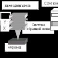 Scanning probe microscope Current state and development of scanning probe microscopy