Calculation of a complex electric circuit of direct current. Calculation and analysis of the electrical circuit of alternating current. Electrical circuit analysis Electrical circuit analysis and calculation
SUMMARY ON THE TOPIC:
METHODS FOR CALCULATION OF DC ELECTRIC CIRCUITS
Introduction
The general task of analyzing an electrical circuit is that, according to the given parameters (EMF, RTD, resistances), it is necessary to calculate the currents, power, voltage in individual sections.
Let us consider in more detail the methods for calculating electrical circuits.
1. Method of Kirchhoff equations
This method is the most general method for solving the problem of electrical circuit analysis. It is based on solving a system of equations compiled according to the first and second Kirchhoff laws for real currents in the branches of the circuit under consideration. Therefore, the total number of equations p is equal to the number of branches with unknown currents. Some of these equations are compiled according to the first Kirchhoff law, the rest - according to the second Kirchhoff law. In a schema containing q nodes, according to the first Kirchhoff law, one can compose q equations. However, one of them (any) is the sum of all the others. Therefore, independent equations compiled according to the first Kirchhoff law will be .
According to the second law of Kirchhoff, the missing m equations, the number of which is equal to ![]() .
.
To write equations according to the second Kirchhoff law, it is necessary to choose m contours so that they eventually include all the branches of the circuit.
Consider this method on the example of a specific circuit (Fig. 1).

First of all, we select and indicate on the diagram the positive directions of currents in the branches and determine their number p. For the scheme under consideration p= 6. It should be noted that the directions of currents in the branches are chosen arbitrarily. If the accepted direction of any current does not correspond to the actual one, then the numerical value of this current is negative.
Therefore, the number of equations according to the first Kirchhoff law is equal to q – 1 = 3.
Number of equations compiled according to the second Kirchhoff law
m = p - (q – 1) = 3.
We select the nodes and circuits for which we will draw up equations, and designate them on the electrical circuit diagram.
Equations according to the first Kirchhoff law:

Equations according to the second Kirchhoff law:

Solving the resulting system of equations, we determine the branch currents. The calculation of an electrical circuit does not necessarily consist in the calculation of currents according to the given EMF of voltage sources. Another formulation of the problem is also possible - the calculation of the EMF of sources for given currents in the branches of the circuit. The task can also have a mixed character - the currents in some branches and the EMF of some sources are given. It is necessary to find currents in other branches and EMF of other sources. In all cases, the number of equations drawn up must be equal to the number of unknown quantities. The circuit may also include energy sources specified in the form of current sources. In this case, the current of the current source is taken into account as the current of the branch when compiling equations according to the first Kirchhoff law.
The circuits for compiling equations according to the second Kirchhoff law must be chosen so that not a single calculated circuit passes through the current source.
Consider the electrical circuit diagram shown in fig. 2.

We select the positive directions of the currents and apply them to the circuit. The total number of circuit branches is five. If we consider the current of the current source J known value, then the number of branches with unknown currents p = 4.
The schema contains three nodes ( q= 3). Therefore, according to Kirchhoff's first law, it is necessary to compose q– 1 = 2 equations. Let's designate the nodes on the diagram. The number of equations compiled according to the second Kirchhoff law m = p - (q – 1) =2.
We select the circuits in such a way that none of them passes through the current source, and designate them on the diagram.
The system of equations, compiled according to the laws of Kirchhoff, has the form:

Solving the resulting system of equations, we find the currents in the branches. The method of Kirchhoff equations is applicable to the calculation of both complex linear and nonlinear circuits, and this is its advantage. The disadvantage of the method is that when calculating complex circuits, it is necessary to compose and solve a number of equations equal to the number of branches p .
The final stage of the calculation is the verification of the solution, which can be done by drawing up the power balance equation.
The power balance of an electric circuit is understood as the equality of the powers developed by all energy sources of a given circuit, and the power consumed by all receivers of the same circuit (the law of conservation of energy).
If there is an energy source with an EMF in the section of the circuit ab and a current flows through this section, then the power developed by this source is determined by the product.
Each of the factors of this product can have a positive or negative sign with respect to the direction ab . The product will have a positive sign if the signs of the calculated values and coincide (the power developed by this source is given to the receivers of the circuit). The product will have a negative sign if the signs and are opposite (the source consumes the power developed by other sources). An example would be a battery in charge mode. In this case, the power of this source (the term ) is included in the algebraic sum of the powers developed by all sources of the circuit, with a negative sign. Similarly, the magnitude and sign of the power developed by the current source are determined. If there is an ideal current source with current in the circuit section mn, then the power developed by this source is determined by the product. As in the EMF source, the sign of the product is determined by the signs of the factors.
Now we can write the general form of the power balance equation
For the circuit shown in Figure 2.2, the power balance equation is
2. Loop current method
The method of loop currents is reduced to the formulation of equations only according to the second Kirchhoff law. The number of these equations, equal to , is less by equations than the number of equations required to calculate electrical circuits using the method of Kirchhoff's laws.
In this case, we assume that in each selected circuit flows independent of each other rated currents, called circuit currents. The current of each branch is defined as the algebraic sum of the loop currents that close through this branch, taking into account the accepted directions of the loop currents and the signs of their values.
The number of loop currents is equal to the number of "cells" (elementary circuits) of the electrical circuit diagram. If the circuit under consideration contains a current source, then independent circuits must be chosen so that the branch with the current source enters only one circuit. For this circuit, the calculation equation is not compiled, since the circuit current is equal to the source current.
The canonical form of writing the equations of loop currents for n independent contours has the form
 where
where
Loop current of the n-th circuit;
The algebraic sum of the EMF acting in the n-th circuit, called the contour EMF;
Own resistance of the n-th circuit, equal to the sum of all resistances included in the circuit under consideration;
Resistance belonging simultaneously to two circuits (in this case, the circuit n and i) and called the common or mutual resistance of these circuits. The first is the index of the contour for which the equation is being compiled. It follows from the definition of mutual resistance that the resistances that differ in the order of the indices are equal, i.e. .
Mutual resistance is assigned a plus sign if the loop currents flowing through them and have the same directions, and a minus sign if their directions are opposite.
Thus, the formulation of the loop current equations can be reduced to writing a symmetrical resistance matrix
![]()
and the contour EMF vector
With the introduction of the vector of the desired loop currents || equations (5) can be written in matrix form
![]()
The solution to the system of linear equations of algebraic equations (5) for the current of the n-th circuit can be found using the Cramer rule
where is the main determinant of the system of equations corresponding to the matrix of loop resistances

The determinant is obtained from the main determinant by replacing the nth column of resistances with a column (vector) of loop EMF.
Consider the method of loop currents using the example of a specific electrical circuit diagram (Fig. 3).

The scheme consists of 3 elementary circuits (cells). Therefore, there are three independent loop currents. We arbitrarily choose the direction of the loop currents and plot them on the circuit. Contours can also be selected not by cells, but there must be three of them (for this scheme) and all branches of the scheme must be included in the selected contours.
For a 3-loop circuit, the equation of loop currents in canonical form is:

We find our own and mutual resistance and contour EMF.
Own resistance of the circuits
![]()
![]()
Recall that intrinsic resistances are always positive.
Let us define mutual resistances, i.e. resistance common to the two circuits.
The negative sign of mutual resistances is due to the fact that the loop currents flowing through these resistances are oppositely directed.
Loop EMF
We substitute the values of the coefficients (resistances) into the equations:

Solving the system of equations (7), we determine the loop currents.
To unambiguously determine the currents of the branches, we select their positive directions and indicate on the diagram (Fig. 3).
Branch currents
3. Method of nodal voltages (potentials)
The essence of the method lies in the fact that nodal voltages (potentials) of independent circuit nodes relative to one node, selected as a reference or basic one, are taken as unknowns. The potential of the basic node is assumed to be zero, and the calculation is reduced to determining (q -1) nodal stresses that exist between the remaining nodes and the basic one.
Nodal stress equations in canonical form with the number of independent nodes n = q -1 have the form

The coefficient is called the intrinsic conductivity of the nth node. Intrinsic conductivity is equal to the sum of the conductivities of all branches connected to the node n .
Coefficient ![]() is called mutual or internodal conduction. It is equal to the sum of the conductivities of all branches, taken with a minus sign, directly connecting the nodes i and n
.
is called mutual or internodal conduction. It is equal to the sum of the conductivities of all branches, taken with a minus sign, directly connecting the nodes i and n
.
The right side of equations (9) is called the nodal current. The nodal current is equal to the algebraic sum of all current sources connected to the node in question, plus the algebraic sum of the products of the EMF sources and the conductivity of the branch with EMF
![]()
In this case, the terms are written with a plus sign if the current of the current source and the EMF of the voltage source are directed to the node for which the equation is being compiled.
The above pattern of determining the coefficients greatly simplifies the formulation of equations, which reduces to writing a symmetric matrix of nodal parameters
and vectors of nodal source currents
![]()
Nodal stress equations can be written in matrix form
![]() .
.
If any branch of a given circuit contains only an ideal source of emf (the resistance of this branch is zero, i.e., the conductivity of the branch is equal to infinity), it is advisable to choose one of the two nodes between which this branch is connected as the basic one. Then the potential of the second node also becomes known and equal in magnitude to the EMF (taking into account the sign). In this case, for a node with a known nodal voltage (potential), the equation should not be drawn up and the total number of system equations is reduced by one.
Solving the system of equations (9), we determine the nodal voltages, and then, according to Ohm's law, we determine the currents in the branches. So for a branch included between nodes m and n the current is

In this case, those quantities (voltages, EMF) are recorded with a positive sign, the direction of which coincides with the selected coordinate direction. In our case (11) - from the node m to node n. The voltage between the nodes is determined through the nodal voltages
![]() .
.
Consider the method of nodal voltages using the example of an electric circuit, the diagram of which is shown in fig. 4.
We determine the number of nodes (in this example, the number of nodes q \u003d 4) and designate them on the diagram.
Since the circuit does not contain ideal voltage sources, any node can be chosen as the base node, for example, node 4.
Wherein .
For the remaining independent nodes of the circuit (q -1=3), we compose the equations of nodal stresses in canonical form.
We determine the coefficients of the equations.
Own conductivities of nodes

Mutual (internodal) conductivities
![]()
Determine the nodal currents.
For 1st node
For 2nd node
 .
.
For 3rd node

Substituting the values of the coefficients (conductivities) and nodal currents into equations (12), we determine the nodal voltages ![]()
Before moving on to determining the currents of the branches, we set them in a positive direction and apply them to the circuit (Fig. 5).
Currents are determined by Ohm's law. So, for example, the current is directed from node 3 to node 1. The EMF of this branch is also directed. Hence

The currents of the remaining branches are determined by the same principle
Since then


4. Principle and method of superposition
The principle of superposition (superposition) is an expression of one of the main properties of linear systems of any physical nature and, as applied to linear electrical circuits, is formulated as follows: the current in any branch of a complex electrical circuit is equal to the algebraic sum of the partial currents caused by each source of electrical energy acting in the circuit in separately.
The use of the superposition principle makes it possible in many circuits to simplify the task of calculating a complex circuit, since it is replaced by several relatively simple circuits, each of which has one energy source.
From the superposition principle follows the superimposition method used for the calculation of electrical circuits.
In this case, the superposition method can be applied not only to currents, but also to voltages in individual sections of the electrical circuit that are linearly related to currents.
The principle of superposition cannot be applied to capacities, since they are not linear, but quadratic functions of the current (voltage).
The superposition principle does not apply to non-linear circuits either.
Let us consider the order of calculation by the superimposition method using the example of determining currents in the circuit of fig. 5.

We arbitrarily choose the direction of the currents and plot them on the circuit (Fig. 5).
If the proposed problem could be solved by any of the methods (MZK, MKT, EOR), then it would be necessary to compose a system of equations. The overlay method makes it possible to simplify the solution of the problem by actually reducing it to a solution according to Ohm's law.
We divide this circuit into two subcircuits (according to the number of branches with sources).
In the first subcircuit (Fig. 6), we consider that only the voltage source acts, and the current of the current source J = 0 (this corresponds to a break in the branch with the current source).

In the second subcircuit (Fig. 7), only the current source operates. The EMF of the voltage source is taken equal to zero E = 0 (this corresponds to the shorting of the voltage source).

Specify the direction of the currents on the subcircuits. In this case, you should pay attention to the following: all currents indicated on the original circuit must also be indicated on the subcircuits. For example, in the subcircuit of Fig. 6, the resistances and are connected in series and the same current flows through them. However, the diagram must indicate the currents and. circuits ELECTRICAL CHAINS PERMANENT TOKA 1.1 Basic...
Payment branched chains permanent current
Test work >> PhysicsTask It is necessary to solve the problem calculation currents in all branches electrical chains permanent current. The task consists of... two parts. The first part of the Calculate task currents branches method ...
Depending on the number of EMF (power) sources in the circuit, its topology and other features, the circuits are analyzed and calculated by various methods. In this case, EMF (voltage) of power sources and circuit parameters are usually known, and voltages, currents and powers are calculated.
In this chapter, we will get acquainted with the methods of analysis and calculation of DC circuits of varying complexity.
Calculation of circuits with one power supply
When there is one active element in the circuit (source of electricity), while others are passive, such as resistors /? t , R 2 ,..., then the chains are analyzed and calculated schema conversion method, the essence of which lies in the transformation (folding) of the original scheme into an equivalent one and subsequent unfolding, during which the required values are determined. We illustrate this method for calculating circuits with series, parallel and mixed connection of resistors.
A circuit with a series connection of resistors. Let's consider this question on the following qualitative example. From an idealized emf source E (R0 = 0), on the output terminals of which there is a voltage u, those. when E=U, through resistors connected in series R ( , R 2 ,..., R n powered load (receiver) with resistance R H(Fig. 2.1, a).
Rice. 2.1
It is required to find the voltage, resistance and power of the circuit equivalent to the given one shown in fig. 2.1, b, making appropriate conclusions and generalizations.
Solution
A. With known resistances and current, the voltages on individual circuit elements, according to Ohm's law, would be as follows:
B. The total voltage (EMF) of the circuit, according to the second law of Kirchhoff, will be written as follows:


D. Multiplying all terms (2-2) by the current / or (2-5) by R, we will have where
B. Dividing all terms (2-2) by the current /, we get where

Formulas (2-3), (2-5), (2-7) show that in a circuit with a single power supply and a series connection of resistances, the equivalent voltage, resistance and power are equal to the arithmetic sums of voltages, resistances and powers of the circuit elements.
The above ratios and conclusions indicate that the original circuit in Fig. 2.1, a with resistances /? 2, R „ can be replaced (collapsed) with the simplest one in Fig. 2.1, b with equivalent resistance R3, determined by expression (2-5).
a) for the scheme according to fig. 2.1, b, the relations U 3 = U = R.I., where R = R3 + R u . Eliminating the current / from them, we obtain the expression
which shows that the voltage U 3 on one of the resistances of the circuit, consisting of two connected in series, is equal to the product of the total voltage U on the ratio of the resistance of this section R3 to the total circuit resistance R. Based on this
b) current and voltage in the price but fig. 2.2, b can be written in different ways:
Solved problems
Task 2.1. What are the resistance, voltage and power of the circuit according to fig. 2.1, and if I= 1A, R x\u003d 1 Ohm, D 2 \u003d 2 Ohm, \u003d 3 Ohm, R u= 4 ohm?
Solution
The voltages across the resistors will obviously be equal: U t =IR^= 1 1 = 1 V, U 2 =IR2 = = 1 2 = 2 V, U n\u003d / L i \u003d 1 3 \u003d 3 V, t / H \u003d ZR H \u003d 1 4 \u003d 4 V. Equivalent circuit resistance: R 3 = R( + /? 9 + R n = 1 + 2 + 3 = 6 ohms. Circuit resistance, voltage and power: /? \u003d &, + /? „ \u003d 6 + 4 \u003d 10 ohms; U \u003d U ( + U 2 + U „ + U n \u003d 1+2 + 3 + 4 = 10 V, or U=IR== 1 10= 10 V; R=W= 10 - 1 = 10W, or P=UJ+ U 2 I + U n I+ U U I= 11+21+31 + + 4 1 = 10 W, or P = PR X + PR 2 + PR a + PR n = 12 1 + 12 2 + 12 3 + 12 4 = 10 W, or R \u003d W / R x + U? 2 /R 2 +UZ /R n +1/2 /R n = 12/1 + 22/2 + 32/3 + 42/4 = 10W.
Task 2.2. In the circuit according to Fig. 2.1, but are known: U = MO B, R ( = Ohm R 2 = 2 ohm, = = 3 ohm, R H = 4 ohm. Define U 2 .
Solution
R=/?! + /?, + L 3 + L 4 \u003d L, + L H \u003d 1+2 + 3 + 4 = 6 + 4 = 10 Ohm 1=11/R= 110/10 = \u003d 11 A, // 2 \u003d L? 2 = 11 2 = 22 V orU 2 \u003d UR 2 / R \u003d110 2 / 10 = 22 V.
Tasks to be solved
Task 2.3. In the circuit according to Fig. 2.1, a known: U = MO B, R^ = Ohm R 2 = 2 ohm, R n= = 3 ohm, R u= 4 ohms. Determine Rn.
Task 2.4. In the circuit according to Fig. 2.1, b are known: U= 110 V U H= 100 V, = 2 ohms. Determine R e.
Task 2.5. In the circuit according to Fig. 2.1.6 known: U= 110 V R t\u003d 3 Ohm, D n \u003d 2 Ohm. Define . Convenient scales for currents and voltages are chosen. First, we build the current vectors on the complex plane (Figure 4), in accordance with the first Kirchhoff law for circuit 2. The addition of vectors is carried out according to the parallelogram rule.

Figure 4 vector diagram of currents
Then we build on the complex plane of the vector of calculated stresses a check according to table 1, figure 5.

Figure 5 Vector diagram of voltages and currents
4.8 Determination of instrument readings
The ammeter measures the current passing through its winding. It shows the effective value of the current in the branch in which it is included. In the circuit (Fig. 1), the ammeter shows the effective value (module) of the current. The voltmeter shows the effective value of the voltage between the two points of the electrical circuit to which it is connected. In the example under consideration (Fig. 1), the voltmeter is connected to the points a and b.
We calculate the stress in complex form:
The wattmeter measures the active power that is consumed in the circuit section enclosed between the points to which the wattmeter voltage winding is connected, in our example (Fig. 1) between the points a and b.
Active power measured by a wattmeter can be calculated by the formula
![]() ,
,
where is the angle between the vectors and .
In this expression, the effective value of the voltage to which the voltage winding of the wattmeter is connected, and the effective value of the current passing through the current winding of the wattmeter.
Or we calculate the total complex power
![]()
wattmeter will show active power R.
4.9 Calculation of resonant circuits
4.9.1 Add an element to the equivalent circuit to obtain voltage resonance. For example, the equivalent circuit represents RL chain. Then you need to add a series-connected capacitor WITH- element. It turns out consistent RLC chain.

4.9.2 Add an element to the equivalent circuit to obtain current resonance. For example, the equivalent circuit represents RL chain. Then you need to add a parallel-connected capacitor WITH- element.

5. Build the circuit in the environment MULTISIM. Put devices and measure currents, voltage and power.
Build the schema in the environment Multisim 10.1. In Figure 6, the working window in the environment Multisim. The instrument panel is located on the right.

Figure 6 working window in the environment Multisim
Place on the working field the elements necessary for the scheme. To do this, on the top toolbar on the left, click the button « place Basic» (See Figure 7). Resistor selection: the window “ Select a Component”, where from the list “ Family" select " resistor". Under the line " Component"Nominal resistance values will appear, select the desired one by pressing the left mouse button or by directly entering into the column" Component» of the desired value. V Multisim standard prefixes of the SI system are used (see Table 1)
Table 1
| Multisim notation (international) | Russian designation | Russian prefix | |

Figure 7
In field " symbol» choose an element. After selection, press the button OK» and place the element on the scheme field by pressing the left mouse button. Then you can continue placing the necessary elements or click the " close" to close the window " Select a Component". All elements can be rotated for a more convenient and visual arrangement on the working field. To do this, move the cursor over the element and press the left mouse button. A menu will appear in which you need to select the option " 90 Clockwise» to rotate 90° clockwise or « 90 CounterCW» to rotate 90° counterclockwise. The elements placed on the field must be connected by wires. To do this, move the cursor over the terminal of one of the elements, press the left mouse button. A wire appears, indicated by a dotted line, we bring it to the terminal of the second element and press the left mouse button again. The wire can also be given intermediate bends, marking them with a mouse click (see Figure 8). The circuit must be grounded.
We connect devices to the circuit. In order to connect a voltmeter, on the toolbar, select " place indicator", in the list FamilyVoltmeter_ V”, transfer the devices to the alternating current (AC) measurement mode.
Current measurement
By connecting all the placed elements, we get the developed scheme drawing.

On the toolbar, select " place Source". In the list " Family» in the window that opens, select the element type « Power Souces', in the list ' Component" - element " DGND».
Voltage measurement

Power measurement


6. Control questions
1. Formulate Kirchhoff's laws and explain the rules for compiling a system of equations according to Kirchhoff's laws.
2. Method of equivalent transformations. Explain the calculation sequence.
3. Power balance equation for a sinusoidal current circuit. Explain the rules for compiling the power balance equation.
4. Explain the procedure for calculating and constructing a vector diagram for your circuit.
5. Stress resonance: definition, condition, signs, vector diagram.
6. Resonance of currents: definition, condition, features, vector diagram.
8. Formulate the concepts of instantaneous, amplitude, average and effective values of sinusoidal current.
9. Write an expression for the instantaneous value of the current in a circuit consisting of elements connected in series R and L if a voltage is applied to the circuit terminals ![]() .
.
10. What values determine the value of the phase angle between voltage and current at the input of a circuit with a serial connection R , L , C ?
11. How to determine from experimental data with series connection of resistances R , X L and X C values Z , R , X , Z TO, R TO, L , X C , C,cosφ , cosφ К?
12. In serial RLC the circuit is set to voltage resonance mode. Will resonance persist if:
a) connect an active resistance in parallel with the capacitor;
b) connect an active resistance in parallel with the inductor;
c) turn on active resistance in series?
13. How should the current change I in the unbranched part of the circuit with a parallel connection of the consumer and the bank of capacitors in the event of an increase in capacitance from WITH= 0 to WITH= ∞ if the consumer is:
a) active
b) capacitive,
c) active-inductive,
d) active-capacitive load?
6. Literature
1. Bessonov L.A. Theoretical foundations of electrical engineering - M .: Higher school, 2012.
2. Benevolensky S.B., Marchenko A.L. Fundamentals of electrical engineering. Textbook for universities - M., Fizmatlit, 2007.
3. Kasatkin A.S., Nemtsov M.V. Electrical engineering. Textbook for universities - M .: V. sh, 2000.
4. Electrical engineering and electronics. Textbook for universities, book 1. / Edited by
V. G. Gerasimov. - M.: Energoatomizdat, 1996.
4. Volynsky B.A., Zein E.N., Shaternikov V.E. Electrical engineering, -M.:
Energoatomizdat, 1987
Annex 1

Scheme group 1

Scheme group 2
Appendix 2
| Z 1 | Z2 | Z3 | Z4 | U |
|
Ministry of Education and Science of the Russian Federation
FGBOU VPO "MATI - Russian State Technological University named after K.E. Tsiolkovsky" (MATI)
Department of Applied Mathematics, Information
technology and electrical engineering”
Coursework on module 1 "Electrical Engineering"
basic discipline for universities "Electrical Engineering and Electronics"
Analysis and calculation of electrical circuits
1MTM-2DB-035
Prokopenko D.A. КР6-25
Completed: "___" _______2017
Handed over to the teacher for verification "___" June 2017.
Checked by: Oreshina M.N. (____________) "___" _______ 2017
Moscow 2017
1.1. Compile a system of calculation equations for determining the currents in the branches of the circuit, using both Kirchhoff laws directly (the method of Kirchhoff laws);
1.1.1 In fig. 1 shows the original Fig. one
DC circuit equivalent circuits
current, the parameters of which are set
1.1.2. Let's transform the circuit to a convenient form and arbitrarily set the positive directions of currents in the branches of the circuit (Fig. 2).

1.1.3. We compose part of the equations of the settlement system, using only the first Kirchhoff law. We select q-1 nodes on the diagram (this diagram contains q=4 nodes, which are marked with Arabic numerals) and for each of them we compose an equation according to the first Kirchhoff law
(node 1) I 3 -I 5 -I 6 =0
(node 2) I 5 -I 2 -I 4 =0
(node 3)I 6 +I 4 +I 1 =0
1.1.4.1. All you need to make p equations in the calculation system ( p- the number of unknown currents, equal to the number of branches in the circuit). Therefore, the number of equations to be written using Kirchhoff's second law is p-(q-1)(for this scheme p=6 and p-(q-1)=3).
1.1.4.2. Choose p-(q-1) independent circuits in the diagram, in each of them we arbitrarily set the direction of bypassing the circuit (marked with round arrows in Fig. 2).
1.1.4.3. For each of the selected contours, we compose an equation using the second Kirchhoff law, as well as Ohm's law ( U=IR)
(circuit I). I 3 R 3 + I 5 R 5 + I 2 R 2 = -E 5
(circuit II). -I 4 R 4 -I 5 R 5 +I 6 R 6 \u003d E 5 -E 6
(circuit III). I 2 R 2 + I 1 R 1 -I 4 R 4 \u003d 0
1.1.5. We combine the resulting equations into a system, which we order and substitute the known parameters
0+0+I 3 +0-I 5 -I 6 =0
0-I 2 +0-I 4 +I 5 +0=0
I 1 +0+0+I 4 +0+I 6 =0
0+12I 2 +20I 3 +0+10I 5 +0=-50
0+0+0-8I 4 -10I 5 +15I 6 =-50
16I 1 +12I 2 +0-8I 4 +0+0=0
Let's find the values of currents using the matrix calculator
I 1 \u003d I 2 \u003d I 3 \u003d ![]() I 4 \u003d I 5 \u003d
I 4 \u003d I 5 \u003d
I 6 = ![]()
First task item1.1. completed.
1.2.1. Using an equivalently transformed circuit (Fig. 2), we arbitrarily set the positive direction of real currents in each branch of the circuit (Fig. 3) (in this example, they are left unchanged).
1.2.2. We select p-(q-1)=3 independent circuits in the circuit, in each of them we arbitrarily set the direction of the circuit current I K1, I K2, I K3 (marked with round arrows in Fig. 3).
1.2.3. Let us compose a system of equations for circuits, in each of which the algebraic sum of the EMF (circuit EMF) is equal to the product of the circuit current of a given cell and the sum of all 
cell resistance, minus the product of the loop currents of neighboring cells and the corresponding resistances of the common branches.
(K1): -E 5 =(R 2 +R 3 +R 5 )I K1 -R 5 I K2 -R 2 I K3
(K2): E 5 -E 6 =(R 4 +R 5 +R 6 )I K2 -R 4 I K3 -R 5 I K1
(K3): 0=(R 1 +R 2 +R 4 )I K3 -R 2 I K1 -R 4 I K2
1.2.4. After substituting the numerical values, we have
-50=42I K1 -10I K 2 -12I K3
-50=-10I K1 +33I K2 -8I K3
0=-12I K1 -8I K2 +36I K3
1.2.5. Solving this system, we find the loop currents:
I K1 =-2.14 A, I K2 =-2.47 A, I K3 =-1.26 A.
1.2.6. We determine the branch currents, guided by the selected directions of the branch currents and the rules:
a) the currents of the external (not having adjacent circuits) branches are equal to the corresponding circuit currents;
b) the currents of the branches are equal to the difference between the loop currents of adjacent cell loops:
I 1 =I K3 =-1.26 A,
I 3 =I K1 =-2.14 A,
I 6 =I K2 = -2.47 A,
I 2 =I K1 -I K3 =-2,14-(-1,26)=-0,88
I 4 =I K3 I K2 =-1,26-(-2,47)=1,21
I 5 =I K1 - I K2 =-2,14-(-2,47)=0,33
The second item of the task is completed.
1.3. Check the correctness of the calculation by determining the currents by the two-node method (nodal voltage method)
The equivalent circuit under consideration contains four nodes, so the two-node method is not directly applicable to the given circuit.
1.3.1. Using the equivalent transformation of the section of the circuit R 2, R 4, R 1 connected according to the “triangle” scheme into the section R 7, R 8, R 9 connected according to the “star” scheme (marked in Fig. 4 by a dotted line), we bring the initial circuit to scheme containing two nodes (Fig. 5).


Rice. 4 Fig. 5
Equivalently combining series-connected R-elements in each branch, we obtain the original circuit for calculation by the two-node method (Fig. 6).

Wherein R 37 =R 3 +R 7 =20+5.3=25.3333 Ω, R 69 =R 6 +R 9 =15+3.5555=18.5555Ω
1.3.2. We arbitrarily set the positive direction of the currents in the branches of the circuit and the positive direction of the nodal voltage U 51 (Fig. 6)
1.3.3. We calculate the conductivity of the branches of the circuit
![]()
![]() .
.
1.3.4. Using the basic formula of the method, we determine the nodal stress
The sign of the terms of the numerator is determined mismatch(+) or match
(-) positive direction and positive direction of the EMF of the considered branch.
1.3.5. We calculate unknown currents in the branches using the generalized Ohm's law
I 37 \u003d -U 51 G 37 \u003d - (-54.1676) * 0.03947 \u003d 2.1379 A,
I 58 \u003d (U 51 + E 5) G 85 \u003d (-54.1676 + 50) * 0.07964 \u003d 0.33 A,
I 69 \u003d (U 51 + E 6) G 69 \u003d (-54.1676 + 100) * 0.5389 \u003d 2.4699 A.
Let's analyze the calculation results. On fig. 5 in each branch, the EMF source and -elements are connected in series. Therefore, the currents in these branches are equal to the calculated ones. However, the sections of the circuit in the vicinity of the sources were not covered by the transformation. Therefore, in accordance with the equivalence condition for the conversion of sections of the circuits, the magnitude of these currents must remain the same as before the conversion. We compare modulo the values of the currents calculated by this method and the method of loop currents
![]()
![]()
![]()
It can be seen that the values of the currents practically coincide. Therefore, both calculations were carried out correctly. The third task has been completed.
1.4. Determine the current flowing through R 2 using the equivalent generator method;
1. We break the sixth branch (Fig. 7) 

Fig.7. Rice. eight.
and arbitrarily set the positive direction of the currents in the remaining branches, the positive direction of the open circuit voltage and the voltage between nodes 1 and 3 (Fig. 8)
2. Determine the value. To do this, we pre-calculate using the two-node method.
Using the basic formula of the method, we determine the nodal stress
![]() .
.
We calculate the currents and, using the generalized Ohm's law
For a contour that includes , we compose an equation according to the second Kirchhoff law (the direction of bypassing the contour is indicated by a round arrow) and calculate
3. We determine the input impedance of the circuit from the side of the terminals of the open branch. To do this, we equivalently convert the section of the circuit connected by a star to the section connected by a triangle.
The converted circuit will look like (Fig. 10) 

Rice. 9. Fig. 10.
![]() .
.
Using the properties of a parallel serial connection - elements, we determine
 .
.
4. Determine the desired current using Ohm's law for a closed circuit
![]() .
.
A similar current calculated by the loop current method is
They practically match. The calculation was done correctly. The fourth item of the task is completed.
INTRODUCTION
The topic of this course work: "Calculation and analysis of electrical circuits."
The course project includes 5 sections:
1) Calculation of DC electrical circuits.
2) Calculation of non-linear DC circuits.
3) Solution of single-phase linear electric circuits of alternating current.
4) Calculation of three-phase linear electrical circuits of alternating current.
5) Study of transient processes in electrical circuits.
Each task includes the construction of diagrams.
The task of the course project is to study various methods for calculating electrical circuits and, based on these calculations, build various types of diagrams.
The following designations are used in the course project: R-resistance, Ohm; L - inductance, H; C - capacitance, F; XL, XC - reactance (capacitive and inductive), Ohm; I - current, A; U - voltage, V; E - electromotive force, V; shu, shi - voltage and current shift angles, deg; P - active power, W; Q - reactive power, Var; S - full power, VA; c - potential, V; NE - non-linear element.
CALCULATION OF LINEAR DC ELECTRIC CIRCUITS
For the electrical circuit (Fig. 1), do the following:
1) Based on the laws of Kirchhoff, compose a system of equations for determining the currents in all branches of the circuit;
2) Determine the currents in all branches of the circuit using the loop current method;
3) Determine the currents in all branches of the circuit based on the method of nodal potentials;
4) Draw up a balance of capacities;
5) Present the results of current calculations for items 2 and 3 in the form of a table and compare;
6) Construct a potential diagram for any closed circuit that includes EMF.
E1=30 V; R4=42 ohm;
E2=40 V; R5=25 ohm;
R1=16 Ohm; R6=52 ohm;
R2=63 Ohm; r01=3 ohm;
R3=34 Ohm; r02=2 ohm;
R1"=R1+r01=16+3=19 ohm;
R2"=R2+r02=63+2=65 Ohm.
Let's choose the direction of the currents.
Let's choose the direction of bypassing the contours.
We compose a system of equations according to the Kirchhoff law:
E1=I1R1"+I5R5-I4R4
E2=I2R2"+I5R5+I6R6
E2=I4R4+I3R3+I2R2"
Figure 1. Schematic of the DC electrical circuit
Calculation of electrical circuits by the method of contour currents.
Let's arrange the currents
We choose the direction of the loop currents according to the EMF
Let's make equations for loop currents:
Ik1 H(R1"+R4+R5)-Ik2ChR4+Ik3R5"=E1
Ik2 H(R3+R+R2")-Ik1ChR4+Ik3H=E2
Ik3 H(R6+R2"+R5)+Ik1HR5+Ik2HR2"=E2
Let us substitute the numerical values of the EMF and resistances into the equation:
Ik1 Ch86-Ik2Ch42-+Ik3Ch25=30
Ik1 Ch42+Ik2Ch141+Ik3Ch65=40
Ik1 Ch(25)+Ik2Ch65+Ik3Ch142=40
We solve the system by the matrix method (Cramer's method):

D1 \u003d 5.273Ch105
D2 \u003d 4.255×10⁵


D3 \u003d -3.877Ch105
We calculate Ik:
We express the currents of the circuit through the contour:
I2 =Ik2+Ik3=0.482+(-44)=0.438A
I4 = -Ik1+Ik2=0.482-0.591=-0.109A
I5 =Ik1 + Ik3=0.591+(-0.044)=0.547A
Let's make a power balance for a given scheme:
Pic.=E1I1+E2I2=(30×91)+(40×38)=35.25W
Rpr. \u003d I12R1 "+ I22R2" + I32R3 + I42R4 + I52R5 + I62R6 \u003d (91) 2H16 + (38) 2H 63 + (82) 2H H34 + (-09) 2H42 + (47) 2H25 + (44) H52 \u003d 41.53 Wts .
1 Calculation of electrical circuits by the method of nodal potentials
2 Arrange the currents
3 Arrange the nodes
4 Let's make an equation for the potentials:
ts1=(1?R3+1?R4+1?R1")-ts2Ch(1/R3)-ts3-(1/R4)=E1?R1"
ts2Ch(1/R3+1?R6+1?R2")-ts1Ch(1/R3)-ts3(1/R2") =(-E2 ?R2")
ts3Ch(1/R5+1?R4+1?R2")-ts2Ch(1/R2")-ts1Ch(1/R4)=E2?R2"
Substitute the numerical values of the EMF and resistances:
c1Ch0.104-c2Ch0.029-c3Ch0.023=1.57
C1Ch0.029+c2Ch0.063-c3Ch0.015=(-0.61)
C1Ch0.023-c2Ch0.015+c3Ch0.078=0.31
5 We solve the system by the matrix method (Cramer's method):

1= = (-7.803×10⁻³)
2= = (-0.457×10⁻³)


3= = 3.336×10⁻³
6 We calculate c:
c2 = = (-21Ch103)
7 Find currents:
I1 \u003d (c4- c1 + E) 1? R1 "= 0.482A
I2 \u003d (c2- c3 + E2)? R2 "= 0.49A
I3= (c1-c2) ?R3=(-0.64)A
I4= (c3- c1) ?R4=(-0.28)A
I5= (c3-c4) ?R5= 0.35A
I6= (c4-c2) ?R6=(-0.023)A
8 The results of current calculation by two methods are presented in the form of a free table
Table 1 - Results of current calculations by two methods
Let's build a potential diagram for any closed circuit including EMF.

Figure 3 - Circuit of the DC electrical circuit
E1=30 V; R4=42 ohm;
E2=40 V; R5=25 ohm;
R1=16 Ohm; R6=52 ohm;
R2=63 Ohm; r01=3 ohm;
R3=34 Ohm; r02=2 ohm;
R1"=R1+r01=16+3=19 ohm;
R2"=R2+r02=63+2=65 Ohm.
We calculate the potentials of all points of the circuit during the transition from element to element, knowing the magnitude and direction of the branch currents and EMF, as well as the resistance values.
If the current coincides in direction with the bypass, then -, if it coincides with the EMF, then +.
c2 \u003d c1-I2R2 "= 0 - 0.438 H 65 \u003d - 28.47B
c3=c2+E2= - 28.47+40=11.53B
c4 \u003d c3-I4R4 \u003d 11.58-(-4.57) \u003d 16.15B
c4 \u003d c4-I3R3 \u003d 16.15-16.32 \u003d -0.17B
We build a potential diagram, plot the resistance of the circuit along the abscissa axis, and the potentials of the points along the ordinate axis, taking into account their signs.
 Selecting a GIS processing program
 Calculation and analysis of an electric circuit of an alternating current
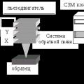 Scanning probe microscope Current state and development of scanning probe microscopy