Writing a simple control program. Creating programs for CNC machines Examples of a CNC program for a turning machine
Parts machined on a CNC machine can be considered as geometric objects. During processing, the rotating tool and the workpiece move relative to each other along a certain path. UE describes the movement of a certain point of the tool - its center. The trajectory of the tool is represented as consisting of separate sections that pass into each other. These sections can be straight lines, arcs of circles, curves of the second or higher orders. The intersection points of these sections are called reference, or nodal, points. As a rule, the UE contains the coordinates of exactly the reference points.
Let's try to write a small program for processing the groove shown in Fig. 3.4. Knowing the coordinates of the reference points, this is not difficult to do. We will not consider in detail the code of the entire UE, but will pay special attention to the writing of lines (frames of the UE) that are directly responsible for moving through the reference points of the groove. To machine a groove, you first need to move the cutter to point T1 and lower it to the appropriate depth. Next, you need to move the cutter sequentially through all the reference points and bring the tool up from the workpiece material. Let's find the coordinates of all reference points of the groove and, for convenience, put them in Table. 3.1.
Table 3.1. Slot reference point coordinates
| Dot | X coordinate | Y coordinate |
|---|---|---|
| Tl | 3 | 8 |
| T2 | 3 | 3 |
| TK | 7 | 3 |
| T4 | 7 | 8 |
Let's bring the cutting tool to the first reference point:
The next two frames cause the tool to descend to the required depth into the workpiece material.
N60 G00 Z0.5
N70 G01 Z-l F25
Once the tool is at the desired depth (1 mm), you can move it through all the reference points to machine the groove:
N80 G01 X3 Y3
N90 G01 X7 Y3
N100 G01 X7 Y8
Now you should remove the tool from the material of the workpiece - raise it to a small height:
Let's put all the frames together, add a few auxiliary commands and get the final version of the program:
| Personnel UP | Frame description |
|---|---|
| % | Program start symbol |
| O0001 (PAZ) | Program number (0001) and program name (PAZ) |
| N10 G21 G40 G49 G54 G80 G90 | Security string |
| N20 M06 T01 (FREZA D1) | Tool call #1 |
| N30 G43 H01 | Tool length compensation No. 1 |
| N40 M03 S1000 | Turning on the spindle speed (1000 rpm) |
| N50 G00 X3 Y8 | Rapid move to reference point T1 |
| N60 G00 Z0.5 | Tool rapid traverse B Z0.5 |
| N70 G01 Z-l F25 | Travel to a depth of 1 mm at a feed rate of 25 mm/min |
| N80 G01 ХЗ Y3 | Moving the tool to point T2 (25 mm/min) |
| N90 G01 X7 Y3 | Moving the tool to point T3 (25 mm/min) |
| N100 G01 X7 Y8 | Moving the tool to point T4 (25 mm/min) |
| N110 G01 Z5 | Tool lift up in Z5 (25 mm/min) |
| N120 M05 | Turn off spindle speed |
| N130 M30 | End of the program |
| % | End of program character |
Significantly increase the productivity of production and the quality of manufactured products. However, they require special programs to work. With their help, models of future products are created and commands are set that regulate the operation of machines. Description of control programs for CNC machines will help you choose the right software.
General information
First of all, to work with such a machine, you will need a 3D editor. When creating homemade medals, numbers or other simple products, you can do without such software. It will be enough to convert the required image into g code. However, layouts of bulk products are created in the appropriate editors.
Volumetric models are created in special software (for example, Art Cam) with subsequent transformation. For industrial devices, it is recommended to use separate software.
The operating system is of great importance. Direct control of the LPT port is important. Software from Microsoft does not have such capabilities (we are talking about Windows operating systems). For some software, delays up to 0.2 seconds will be normal. However, software such as MATH 3, for example, cannot be used in the presence of such delays (the machine may be damaged).
CNC programs work much better in a Linux environment. There is even a CNC Linux operating system specially created for such activities. It is optimized for normal machine operation by using the LPT port.
Software list
The amount of software for CNC is large. It differs in its functionality and purpose. Some software requires powerful computers. Other samples are able to work on less powerful computers.
The following software can be distinguished:
- "Visual CAD/CAM 2014". This is a software package that includes the software necessary to create control programs for 3-axis milling machines. In addition, this package contains tools that visualize the processing process;
- "Feature CAM 2011". One of the most well-known utilities that are used for modeling and manufacturing products of complex design, and industrial equipment. The automotive, aerospace, engineering and energy industries have been using this software for years;
- Gibbscam. Designed for two to five axial milling cutters. With this software, you can also do several types of modeling (2D, 3D, surface, wireframe, etc.);
- Art CAM. The best utility with which you can design volumetric reliefs. A notable feature of this software is the absence of the need for further manual refinement.
The CNC programs listed above do the job well. For several years they have been used by various enterprises around the world.
MATH 3
Separately, it is worth mentioning the American software "MATH 3". It is suitable for various types of routers, plotters and lathes. Widely used by both professionals and amateurs.
With this program for a CNC milling machine, you can:
- manage multiple coordinates (up to six);
- import graphic images of different formats directly;
- create control software;
- manage an indicator such as rotational speed;
- use manual pulse generators;
- create custom M codes.
To use this software, you must have CNC Linux OS. Otherwise, it will not be possible to ensure the correct operation of the software.

Creation of control software
The process of creating a CNC control program consists of several stages. An example is the creation of a project for woodcarving. CNC machines are programmed in a bundle of CAD / CAM software, so the whole work process will consist of three stages:
- Creation of a product model. For this, 3D editors are used. The work is carried out by specially trained designers, whose services will need to be resorted to. The created model can be embodied in the future in different scales and sizes.
- Creation of a control program. For this, the software described above is used. The finished model of the future product is imported into the selected software. In accordance with its size, shape, type and other parameters, the corresponding software is compiled.
- Milling. The commands of the control program are read by the machine, due to which the working organs of the device move along pre-created coordinates, performing the prescribed actions.
Working with a CNC machine requires certain knowledge. However, the availability of special software makes this task easier.
Thus, the operation of machine tools with numerical control is impossible without special utilities. They are created using separate software. Today there is a large number of such software. Different software differs both in functionality and in requirements for a computer. Although some knowledge is required to operate the software, numerous instructions make the learning process easier.
CNC machine canned cycles
Rice. 8.8. It is necessary to drill 7 holes with a diameter of 3 mm and a depth of 6.5 mm
Example #2

Rice. 8.9. It is necessary to drill 12 holes with a diameter of 5 mm and a depth of 40 mm, first perform the hole centering operation
| Program code | Description |
| % O0002 (PROGRAM NAME - HOLES2) N100 G21 N102 G0 G17 G40 G49 G80 G90 (CENTROVKA) N104 T1 M6 N106 G54 X21.651 Y12.5 S1200 M3 N108 G43 h2 Z100. N110Z2. N112 G99 G81 Z-.8 R2. F70. N114 X12.5 Y21.651 N116 X0. Y25. N118 X-12.5 Y21.651 N120 X-21.651 Y12.5 N122 X-25. Y0. N124 X-21.651 Y-12.5 N126 X-12.5 Y-21.651 N128 X0. Y-25. N130 X12.5 Y-21.651 N132 X21.651 Y-12.5 N134 X25. Y0. N136 G80 N138 Z100. N140 M5 N142 G91 G28 Z0. N144 G28 X0. Y0. N146 M01 (DRILL 12 HOLES) N148 T2 M6 N150 G54 X21.651 Y12.5 S1000 M3 N152 G43 h3 Z100. N154Z2. N156 G99 G83 Z-40. R2. Q2. F45. N158 X12.5 Y21.651 N160 X0. Y25. N162 X-12.5 Y21.651 N164 X-21.651 Y12.5 N166 X-25. Y0. N168 X-21.651 Y-12.5 N170 X-12.5 Y-21.651 N172 X0. Y-25. N174 X12.5 Y-21.651 N176 X21.651 Y-12.5 N178 X25. Y0. N180 G80 N182 Z100. N184 M5 N186 G91 G28 Z0. N188 G28 X0. Y0. N190 M30% | Program number Program name Metric operation Safety line Comment Centering call Move to hole no. 1 Tool length compensation Rapid move to Z2. Drilling Canned Cycle Hole Centering #2 Hole Centering #3 Hole Centering #4 Hole Centering #5 Hole Centering #6 Hole Centering #7 Hole Centering #8 Hole Centering #9 Hole Centering #10 Hole Centering #11 Hole Centering #12 Canned Cycle Cancel Move to Z100. Spindle stop Return to Z origin Return to X, Y origin Temporary stop Comment Call 5mm drill Move to hole No. 1 Tool length compensation Rapid move to Z2. Intermittent drilling cycle Drill hole #2 Drill hole #3 Drill hole #4 Drill hole #5 Drill hole #6 Drill hole #7 Drill hole #8 Drill hole #9 Drill hole #10 Drill hole #11 Drill hole #12 Canned cycle cancel Move to Z100. Spindle stop Z origin return X, Y origin return Program end |
planetacam.ru
2.17. Example of a control program for processing
details "Threaded roller"
On fig. 41 shows a combined drawing of the workpiece and the “Threaded roller” part with the trajectories of the cutting tools for its processing on a 16A20F3 machine equipped with a 2P22 CNC system.

Rice. 41. Scheme for processing the part "Threaded roller"
The control program for processing the part "Threaded roller" has the following form:
| N001 T1S3 572 F0.43 M08 | Cutter T1 - rough, third range, n = 572 rpm, s = 0.43 mm / rev, coolant supply on. |
| Approach to the starting point for the cycle L08. |
|
| N003 L08 A1 P4 | Cycle L08, finishing allowance 1 mm per diameter, depth of cut 4 mm. |
| Description of the contour of the part. |
|
| N011 S3 650 F0.2 | Mode change n = 650 rpm, s = 0.2 mm/rev. |
| Starting point before rough end trimming. |
|
| Rough cutting of the end face according to the cycle L05. |
|
| N014 T3 S3 1000 F0.12 | Cutter T3 - finishing, third range, n = 1000 rpm, s = 0.12 mm / rev. |
| Approach to the starting point for the cycle L10. |
|
| Setting a constant cutting speed. |
|
| Defining cycle L10 for finishing, part description from block N004. |
|
| Cancel constant cutting speed. |
|
| The starting point before the finish end cut. |
|
| Clean end cut. |
|
| Retraction of the cutter from the end along the Z axis by 0.5 mm. |
|
| Approach of the cutter to the point of the beginning of the chamfer 2×45°. |
|
| Chamfer turning 2×45°. |
|
| N024 T5 S3 600 F0.25 | T5 cutter - grooving, third range, n = 600 rpm, s = 0.25 mm/rev. |
| N025 X32 Z-35 E | Starting point before grooving. |
| Grooving up to ø20 mm. |
|
| The withdrawal of the cutter from the groove is accelerated. |
|
| N028 T7 S3 720 F0.3 | T7 cutter - threaded, third range, n = 720 rpm, s = 0.3 mm / rev. |
| Starting point of the cycle before threading. |
|
| N030 L01 F1.5 W-33.5 A0 X22.08 P0.3 C0 | Cycle L01 for threading M24×1.5. |
| Turn off the coolant supply. |
|
| End of control program, return to I.T. |
3. Work on machines equipped with a 2p22 CNC system
3.1. Remote Control
To set the operating modes of the CNC 2P22 device, manual data entry, program editing, and dialogue with the device, a control panel is designed, made in the form of a remote unit installed on the rotating console of the machine. The keyboard of the control panel is shown in fig. 17, and the assignment of the keys - in table. 3.
The functions performed in the main and auxiliary modes of operation of the 2P22 CNC device are given in Table. 7.
Table 7
Operating modes of the CNC 2P22
| Working mode |
||
| basic | auxiliary |
|
| Part processing according to the control program | Automatic mode
| |
| Part processing according to the control program with stops at the end of the block | Automatic mode
| Frame mode
|
| Drawing up a program according to a model, recruiting and working out individual personnel | Manual mode
| |
| Reference system binding | Manual mode
| Mode "Exit to a fixed point of the machine"
|


Continuation of the table. 7
| Semi-automatic memory entry of floating zero and tool overhangs | Manual mode
|
|
| Semi-automatic entry into the home position memory | Manual mode
| Mode "Semi-automatic input of constants"
|
| Exit to the starting position | Manual mode
| Mode "Exit to initial position"
|
| Entering the control program from the control panel, displaying and editing programs | Input mode
| |
| Entering, displaying and editing tool overhangs, floating zero, home position, machine parameters | Input mode
| Mode "Entering constants"
|
| Search for the required block number of the technological program and its indication | Input mode
| Frame search mode |
| Entering a technological program from a magnetic tape | Input mode
|
|
| Entering a technological program from punched tape | Output mode
| "External" mode carrier-perforated tape"
|


 ,
, 


The end of the table. 7
| Outputting a Program to Tape | Output mode
| Mode "External media - magnetic tape"
|
| Outputting the program to punched tape | Output mode
| "External" mode carrier - perforated tape "
|
| Checking the performance of the device according to the tests embedded in the software | Test mode
| Diagnostic mode
|
| Entering Tests from Magnetic Tape | Test mode
| Mode "External media - magnetic tape"
|
| Entering tests from punched tape | Test mode
| Mode "External media - punched tape"
|
| Indication of sensors and the status of exchange signals at the input and output connectors of the CNC device | Test mode
| Mode "Indication of electroautomatics of the machine"
|
| Reset status indication exchange signals | Test mode
| Mode "Reset indication of electroautomatics of the machine"
|


To perform, presented in table. 7 functions, it is necessary to exit to the corresponding operation mode (main and auxiliary) by pressing the given keys on the control panel of the CNC device.
Keys that continue to work after they are released have a light signaling. Keys for selecting the main modes 3, 4, 5, 6, 7 have a dependent inclusion, i.e. only one of them is active at a time. The action of the remaining keys with light signaling is canceled by pressing it again.
studfiles.net
Programming in ISO
Examples of control programs
It is necessary to create a NC for processing the outer contour of the part (Fig. 11.1) with a cutter with a diameter of 5 mm without compensation for the tool radius. Milling depth - 4 mm. The contour is approached along a straight section.
| % O0001 (PROGRAM NAME - CONTOUR1) N100 G21 N102 G0 G17 G40 G49 G80 G90 (FREZA D5) | Program O0001 Comment - program name Metric data input mode Security line Comment - cutter Ф5 mm Tool call #1 |
 Rice. 11.1. contouring Rice. 11.1. contouring |
|
| N106 G0 G90 G54 X25. Y-27.5 S2000 M3 N108 G43 h2 Z100. N110Z10. N112 G1 Z-4. F100. N116 X-27.5 N118 Y20. N120 G2 X-20. Y27.5 R7.5 N122 G1 X1.036 N124 X27.5 Y1.036 N126 Y-20. N128 G2 X20. Y-27.5 R7.5 N130 G1 Z6. N132 G0 Z100. N134 M5 N136 G91 G28 Z0. N138 G28 X0. Y0. N140 M30 | Positioning to the starting point of the path (1), turning on the spindle speed of 2000 rpm Tool length compensation #1 Positioning in Z10 The cutter descends to Z-4 at a cutting feed of 100 mm/min Linear movement to a point (2) Linear movement to a point (3 ) Arc motion to point (4) Linear motion to point (5) Linear motion to point (6) Linear motion to point (7) Arc motion to point (8) Cutter rises to Z6 Cutter rises at rapid feed to Z100 Stop spindle Return to the origin in Z Return to the origin in X and Y End of program |
Example #2. Contouring with tool radius compensation
It is necessary to create a NC for processing the outer contour of the part (Fig. 11.2) with a cutter with a diameter of 5 mm with compensation for the tool radius. Milling depth - 4 mm. The contour is approached tangentially.
| % O0002 (PROGRAM NAME - CONTOUR2) N100 G21 N102 G0 G17 G40 G49 G80 G90 (FREZA D5) N104 T1 M6 N106 G0 G90 G54 X25. Y-35. S2000 M3 N108 G43 h2 Z100. | Program O0002 Comment - program name Metric data input mode Safety line Comment - cutter Ф5 mm Call tool #1 Positioning to the starting point of the trajectory (1), turning on the spindle speed of 2000 rpm Tool length compensation #1 Positioning in Z10 |
 Rice. 11.2. Contouring with correction Rice. 11.2. Contouring with correction |
|
| N112 G1 Z-4. F100. N114 G41 D1 Y-30. N116 G3 X20. Y-25. R5. N118 G1 X-25. N120Y20. N122 G2 X-20. Y25. R5. N124 G1 X0. N126X25. Y0. N128 Y-20. N130 G2 X20. Y-25. R5. N132 G3 X15. Y-30. R5. N134 G1 G40 Y-35. N136Z6. N138G0Z100. N140 M5 N142 G91 G28 Z0. N144 G28 X0. Y0. N146 M30 | Cutter descends to Z-4 at cutting feed of 100 mm/min Left offset, move to point (2) Tangential approach to point (3) Linear move to point (4) Linear move to point (5) Arc move to point (6) Linear movement to a point (7) Linear movement to a point (8) Linear movement to a point (9) Arc movement to a point (10) Retraction of the tool from the contour tangentially to a point (11) Linear movement to a point (12) with override canceled Cutter rises to Z6 Cutter rises at rapid traverse to Z100 Spindle stop Return to origin in Z Return to origin in X and Y End of program |
Example #3. contouring
It is necessary to create a NC for finishing the pocket (Fig. 11.3) without compensation for the tool radius with a cutter with a diameter of 5 mm. Milling depth - 2 mm. The contour is approached tangentially.
| % O0003 (PROGRAM NAME - FINISH POCKET) N100 G21 N102 G0 G17 G40 G49 G80 G90 (FREZA D5) N104 T1 M6 N106 G0 G90 G54 X-2.5 Y-2.5 S1000 M3 N108 G43 h2 Z100. N110Z10. N112 G1 Z-2. F100. N114 Y-5. N116 G3 X0. Y-7.5 R2.5 N118 G1 X10. N120 G3 X17.5 Y0. R7.5 | Program O0003 Comment - program name Metric data input mode Safety line Comment - cutter Ф5 mm Call tool no. 1 Positioning to the starting point of the path (1), turn on the spindle speed Tool length compensation No. 1 Positioning in Z10 The cutter goes down to Z-2 at cutting feed 100 mm/min Linear movement to a point (2) Tangential approach to a point (3) Linear movement to a point (4) Moving along an arc to a point (5) |
 Rice. 11.3. Pocket finishing Rice. 11.3. Pocket finishing |
|
| N122X10. Y7.5 R7.5 N124 G1 X-10. N126 G3 X-17.5 Y0. R7.5 N128 X-10. Y-7.5 R7.5 N130 G1 X0. N132 G3 X2.5 Y-5. R2.5 N134 G1 Y-2.5 N136 Z8. N138G0Z100. N140 M5 N146 M30 | Arc move to point (6) Linear move to point (7) Arc move to point (8) Arc move to point (9) Linear move to point (10) Tool retraction tangential to point (11) Linear move to point (12) The cutter rises to Z8 The cutter rises in rapid traverse to Z100 Spindle stop End of program |
Example number 4. Contouring with tool radius compensation
You need to create a NC for finishing a pocket with tool radius compensation. Milling depth - 2 mm. The contour is approached tangentially.
| % O0004 (PROGRAM NAME - FINISH POCKET2) | Program O0004 Comment - program name Metric input mode |
 Rice. 11.4. Pocket finishing with correction Rice. 11.4. Pocket finishing with correction |
|
| N102 G0 G17 G40 G49 G80 G90 N104 T1 M6 N106 G0 G90 G54 X-2.5 Y-5. S1000 M3 N108 G43 h2 Z100. N110Z10. N112 G1 Z-2. F100. N114 G41 D1 Y-7.5 N116 G3 X0. Y-10. R2.5 N118 G1 X10. N120 G3 X20. Y0. R10. N122X10. Y10. R10. N124 G1 X-10. N126 G3 X-20. Y0. R10. N128 X-10. Y-10. R10. N130 G1X0. N132 G3 X2.5 Y-7.5 R2.5 N134 G1 G40 Y-5. N136Z8. N138G0Z100. N140 M5 N146 M30 | Safety line Call tool no. 1 Position to path start point (1), turn on spindle speed Tool length compensation no. tangent to point (3) Linear move to point (4) Arc move to point (5) Arc move to point (6) Linear move to point (7) Arc move to point (8) Arc move to point (9) Linear move to point (10) Tool retraction tangential to point (11) Linear move to point (12) with override canceled Cutter rises to Z8 Cutter rises at rapid feed to Z100 Spindle stop Program end |
Example number 5. Milling a rectangular pocket
It is necessary to create a NC for processing a rectangular pocket with a cutter with a diameter of 10 mm. Milling depth - 1 mm.
| % O0005 (PROGRAM NAME - ROUGH POCKET) N100 G21 N102 G0 G17 G40 G49 G80 G90 | Program O0005 Comment - program name Metric data input mode Security string Tool call #1 |
 Rice. 11.5. Rough milling of a rectangular pocket Rice. 11.5. Rough milling of a rectangular pocket |
|
| N106 G0 G54 X-13.75 Y3.75 S1000 M3 N108 G43 h2 Z100. N110Z10. N112 G1 Z-1. F100. N114 Y-3.75 N116 X13.75 N118 Y3.75 N120 X-13.75 N122 X-17.5 Y7.5 N124 Y-7.5 N126 X17.5 N128 Y7.5 N130 X-17.5 N132 X-25. Y15. N134 Y-15. N136X25. N138Y15. N140 X-25. N142Z9. N144 G0 Z100. N146 M5 N152 M30 | Positioning to the starting point of the path (1), turning on the spindle speed Tool length compensation No. 1 Positioning in Z10 The cutter descends to Z-1 at a cutting feed of 100 mm/min Linear movement to point (2) Linear movement to point (3) Linear movement to (4) Linear move to point (1) Linear move to point (5) Linear move to point (6) Linear move to point (7) Linear move to point (8) Linear move to point (5) Linear move to point (9) Linear movement to point (10) Linear movement to point (11) Linear movement to point (12) Linear movement to point (9) Cutter rises to Z9 Cutter rises at rapid feed to Z100 Spindle stop End of program |
Example number 6. Milling a round pocket
It is necessary to create a NC for processing a round pocket with a cutter with a diameter of 10 mm. Depth - 0.5 mm.
| % O0000 (PROGRAM NAME - N6) N100 G21 N102 G0 G17 G40 G49 G80 G90 | Program O0006 Comment - program name Metric data input mode Security string |
 Rice. 11.6. Rough milling of a round pocket Rice. 11.6. Rough milling of a round pocket |
|
| N104 T1 M6 N106 G0 G90 G54 X0. Y0. S1000 M3 N108 G43 h2 Z100. N110Z10. N112 G1 Z-.5 F100. N120X5. F200 N122 G3 X-5. R5. N124X5. R5. N126 G1 X10. N128 G3 X-10. R10. N130X10. R10. N132 G1X15. N134 G3 X-15. R15. N136X15. R15. N138 G1 Z10 F300. N140 G0 Z100. N142 M5 N148 M30 | Calling tool no. 1 Positioning to the starting point of the path (1), turning on the spindle speed Tool length compensation no. orbit” … Move to point (2) Circular move in 2nd “orbit” … Move to point (3) Circular move in 3rd “orbit” … Cutter rises to Z10 Cutter rises at rapid traverse to Z100 Spindle stop End of program |
planetacam.ru
Writing a simple control program
Introduction to Machining ProgrammingParts machined on a CNC machine can be considered as geometric objects. During processing, the rotating tool and the workpiece move relative to each other along a certain path. UE describes the movement of a certain point of the tool - its center. The trajectory of the tool is represented as consisting of separate sections that pass into each other. These sections can be straight lines, arcs of circles, curves of the second or higher orders. The intersection points of these sections are called reference, or nodal, points. As a rule, the UE contains the coordinates of exactly the reference points.

Rice. 3.3. Any detail can be represented as a set of geometric elements. To create a processing program, it is necessary to determine the coordinates of all reference points
Let's try to write a small program for processing the groove shown in Fig. 3.4. Knowing the coordinates of the reference points, this is not difficult to do. We will not consider in detail the code of the entire UE, but will pay special attention to the writing of lines (frames of the UE) that are directly responsible for moving through the reference points of the groove. To machine a groove, you first need to move the cutter to point T1 and lower it to the appropriate depth. Next, you need to move the cutter sequentially through all the reference points and bring the tool up from the workpiece material. Let's find the coordinates of all reference points of the groove and, for convenience, put them in Table. 3.1.
Table 3.1. Slot reference point coordinates
Hello dear read. In this topic, we will consider one of the most pressing issues for a CNC machine, namely, how to learn how to write a program for a beginner for a CNC machine. The word novice means a person who has absolutely no knowledge in this field of activity. I ask people who work in this area for a long time not to strongly criticize this article, because it is intended for people with a minimum level of knowledge.
1 What is a CNC machine and what are programs for?
Let's start from afar. If you are new to this field, then you will need to know what a CNC machine is. A CNC machine is a numerically controlled machine that does work according to a planned program you create.
Nowadays, there are a huge number of programs that can help you develop your projects. But you still need knowledge, which is also a starting point. Due to problems with programs or simple ignorance of their functions, small in-house enterprises burn out, or increased costs for materials for production. Therefore, I will try to explain you the starting basics that will help you in further development.
2 TOP-3 most popular programs for learning and working with a CNC machine.
To begin with, we will display the most popular and useful programs for working with a machine tool with programmable numerical control.
Mach3 ranks 3rd in our top apps. This application took 3rd place for a reason.
Firstly, this program can be found for free on the Internet, while spending a little of your time and effort.
Secondly, this program, designed to work with a machine tool with programmable numerical control, has an additional user manual that describes all the functions and features for using the program.
Thirdly, the program has a simple and intuitive interface that will not cause your brain to freeze. This speeds up getting used to the program, and reduces the time for project development.
Here are the benefits of the Mach3 program. But still, the program is intended for people who can work at least with a manual or automatic machine, but not for absolute beginners. By the way, a full description of this program can be found on our website.
The second place is occupied by the CNCez Pro program.
This program allows you to work in a CNC machine simulator, but you can also create programs in it, which can then be directly transferred to a CNC machine. Just like Mach3, it has a huge set of functions and commands, but finding it in a free Internet resource is quite difficult and problematic. I can tell you from my own experience that you will spend more than one day looking for her, but they are worth it. After all, when working in this simulator, only electricity is spent and nothing more. It also comes with a user manual to help you get started. This is what the CNCez Pro simulator is all about.
And now let's move on to the climactic part of our article and let's say which program takes first place in our top. The first place was taken by a program called ArtCam.
This application is directly related to the CNC machine tool. This application has a huge number of different tools and functions built into it. Also, the program has an item for creating three de models, as well as other interesting items. The program includes writing programs for the CNC machine. But this program has one drawback. Finding this program in a free source is unrealistic, and the cost of the program is quite high. But the cost is offset by the various capabilities of this program for a CNC machine. There is also a choice of your preparedness, which plays a huge role in your starting training and therefore it took first place in the top programs suitable for learning to work with a numerically controlled machine tool.
3 Why you should use these programs.
We advise you all to use these applications, because these programs have gone through fire and water, as well as various prevention tests. Applications for working with machine tools with numerical control are constantly being developed and upgraded, which adds more and more new features. When I started working with a CNC machine, I faced the problem of writing programs to create a product. But in just a month, I studied the starter manual for Mach3 and learned how to develop my own programs for making products. Now I have already built up a starting audience of buyers and work for myself, but it all takes time, resources, and most importantly, you need to constantly improve.
4 Result of the article:
Dear readers, in this article we examined the CNC machine and the development of programs for creating a variety of products. Of course, working with CNC machine tool applications is difficult and problematic. But any problem can be studied and solved with the help of improvised materials. If there is a problem with a lack of knowledge, then you can read additional literature, as well as study additional guidance for various programs. To achieve a certain goal, you need to set goals that you can achieve. For beginners in this field, I can give only one advice - study as much additional literature as possible. It will help you to work with a machine tool with numerical programmable control, and you will also be able to improve yourself in the practical part. I hope my advice will help you and you will achieve maximum success in writing programs for CNC machines. I wish you all good luck, success and wealthy customers. Farewell dear readers.
You can write control programs on a computer in a notebook, especially if you are good at mathematics and have a lot of free time. Or you can immediately on the machine, and let the whole shop wait, and you don’t feel sorry for the extra workpiece. There is a third way of writing - they haven’t come up with a better one yet.
The CNC machine processes the workpiece according to the program in G-codes. G-code is a set of standard commands that CNC machines support. These commands contain information about where and how fast to move the cutting tool to machine the part. The movement of the cutting tool is called a path. The tool path in the control program consists of segments. These segments can be straight lines, circular arcs, or curves. The intersection points of such segments are called reference points. The text of the control program displays the coordinates of reference points.
Program example in G-codes
|
Program text |
Description |
|
Set parameters: machining plane, zero point number, absolute values |
|
|
Calling tool number 1 |
|
|
Turning on the spindle - 8000 rpm |
|
|
Rapid to point X-19 Y-19 |
|
|
Accelerated movement to height |
|
|
Linear movement of the tool to XZ point Y3 with feed F = 600 mm/min |
|
|
Move the tool along an arc with a radius of 8 mm to the point X8 Y3 |
|
|
Spindle shutdown |
|
|
End of the program |
There are three methods for programming CNC machines:
- Manually.
- On the machine, on the CNC stand.
- in the CAM system.
Manually
For manual programming, the coordinates of reference points are calculated and the sequence of movement from one point to another is described. This is how you can describe the processing of simple geometry, mainly for turning: bushings, rings, smooth stepped shafts.
Problems
Here are some problems that are encountered when a program is written to the machine by hand:
- For a long time. The more lines of code in the program, the higher the labor intensity of manufacturing the part, the higher the cost of this part. If the program is more than 70 lines of code, then it is better to choose a different programming method.
- Marriage. We need an extra blank for implementation in order to debug the control program and check for gouges or undercuts.
- Breakage of equipment or tools. Errors in the text of the control program, in addition to marriage, can also lead to breakage of the machine spindle or tool.
Parts for which programs are written by hand have a very high cost.
On a CNC stand
On the CNC stand, the processing of the part is programmed in an interactive mode. The machine setter fills in the table with the processing conditions. Specifies which geometry to process, width and depth of cut, approaches and departures, safe plane, cutting conditions and other parameters that are individual for each type of processing. Based on this data, the CNC rack generates G commands for the tool path. This is how simple body parts can be programmed. To check the program, the installer starts the simulation mode on the CNC stand.
Problems
Here are some of the problems encountered when a program is written on a rack:
- Time. The machine does not work while the installer writes a program for processing the part. Machine downtime is wasted money. If the program gets more than 130 lines of code, then it is better to choose a different programming method. Although on a CNC stand, of course, writing a program is faster than manually.
- Marriage. The CNC stand does not compare the result of the machining with the 3D model of the part, so the simulation on the CNC stand does not show gouges or positive oversize. To debug the program, you need to lay an extra workpiece.
- Not suitable for complex parts. On the CNC stand, you cannot program the processing of complex-profile parts. Sometimes, for specific parts and sizes, manufacturers of CNC racks make special operations on order.
While the program is being created on the rack, the machine does not bring money to production.
In SprutCAM
SprutCAM is a CAM system. CAM is short for Computer-Aided Manufacturing. This is translated as "manufacturing using a computer." A 3D model of a part or a 2D contour is loaded into SprutCAM, then the sequence for manufacturing the part is selected. SprutCAM calculates the cutting tool path and outputs it in G-codes for transfer to the machine. A postprocessor is used to output the toolpath to G-code. The postprocessor translates the internal SprutCAM commands into G-code commands for the CNC machine. It looks like
for translation from a foreign language.
The principle of operation in SprutCAM is presented in this video:
Advantages
Here are the advantages when working with SprutCAM:
- Quickly. Reduces time to create programs for CNC machines by 70%.
- Implementation without unnecessary preparation. The program is checked before running on the machine.
- Excludes marriage. According to our users, SprutCAM reduces the occurrence of defects by 60%.
- Collision control. SprutCAM controls collisions with a part or working units of the machine, plunges at rapid feed.
- Processing of complex profile parts. In SprutCAM for multi-axis operations, 13 strategies for moving the tool along the surface of the part and 9 strategies for controlling the tool axis are used. SprutCAM automatically controls the angle of inclination and calculates a safe machining path so that there is no collision of the holder or cutting tool with the workpiece.
Drawing up a control program for your CNC machine is possible in the full-featured version of SprutCAM. It needs to be downloaded and run. After installation, you will need to register. Immediately after registration, SprutCAM will start working.
For those who have just started trying, we provide a 30-day full-featured free version of the program!
SprutCAM is 15 configurations, including two special versions: SprutCAM Practice and SprutCAM Robot. To find out which configuration is suitable for your equipment and how much it costs, call 8-800-302-96-90 or write to [email protected] site.
 Selecting a GIS processing program
 Calculation and analysis of an electric circuit of an alternating current
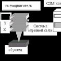 Scanning probe microscope Current state and development of scanning probe microscopy