Linear feedback shift register. Linear Shift Register with Feedback Linear Shift Register Example
To build stream ciphers, sequences on shift registers are very often used. A feedback shift register consists of two parts: a shift register and a feedback function, as shown in Fig. 87. The shift register itself is a sequence of bits, the number of which determines the length of the register. So, if n bits are involved in the register, then they say that the n-bit shift register. Each time a bit is retrieved, all bits of the shift register are shifted to the right by one position, usually towards the least significant bits. The period of the shift register is the length of the resulting sequence before it begins to repeat.
Rice. 87.
Any mathematical function that performs an operation on bits can act as feedback. The simplest type of feedback shift register is the linear feedback shift register (LFSR). In LFSR, feedback is simply a modulo 2 addition (XOR) operation on some bits of a register; the list of these bits is called a sequence of taps, or pickup points, as shown in fig. 88. Sometimes such a pattern is called a Fibonacci configuration. Due to the simplicity of the feedback sequence, a fairly developed mathematical theory can be used to analyze LFSR. In any case, the quality of the produced SRP is evaluated by a special set of tests.

Rice. 88.
LFSR are written in the form of polynomials. In this case, the degree of the first element of the polynomial indicates the number of bits in the shift register, and the exponential exponents of the remaining members of the polynomial indicate which pickup points will be used. So, for example, writing x 4 + x + 1 means that a register of four elements will be used, for which bits bi and b 0 will participate in the formation of feedback (Fig. 89).

Rice. 89.4
Consider the operation of the register shown in Fig. 89. Initialize it, for example, with the value 0101 (the initial initialization can be performed by any sequence of bits, except for a sequence of only zeros, since in this case the feedback will always form a value of zero and the register will not produce the expected PSP). So, in the register there is a shift to the right by one position. The least significant bit, equal to 1, is forced out of the register and forms the first bit of the PRS. Those bits that were in positions b, and b 0 before the shift are added modulo 2 and form a new
high bit of the register. An illustrative example of the operation of the considered LFSR is shown in fig. 90.

Rice. 90.
As can be seen from fig. 90, the register filling will go through a weight of 15 out of 16 possible states (we previously determined that the sixteenth state, when LFSR is 0000, cannot be considered). After that, the filling of the register will again be equal to the initial value of 0101, and the generation of the bit sequence will begin to repeat. The output sequence of the register will be the string of least significant bits (up to the horizontal line in Fig. 90): 101011110001001. The size of the bit sequence before it is repeated is called the period. To ensure the maximum period of a particular LFSR (i.e., for the register to go through all the possible internal states), the polynomial that determines the operation of the register must be primitive modulo 2. As with large primes, there is no way to generate such polynomials. One can only take a polynomial and check whether it is irreducible modulo 2 or not. In the general case, a primitive polynomial of degree n is such an irreducible polynomial that is a divisor of x 2 "+1, but is not a divisor of xd +1 for all d that are divisors of 2 "-1. B. Schneier provides a table of some polynomials, which are irreducible modulo 2.
Summarizing the knowledge obtained as a result of considering the example of the operation of LFSR (Fig. 90), we can say that the n-bit LFSR can be in one of the 2”-1 internal states. Theoretically, such a register can generate a pseudo-random sequence with a period of 2 n -1 bits. Such registers are called LFSR registers with a maximum period. The resulting output is called a t-sequence.
Ministry of Education and Science
RUSSIAN STATE SOCIAL UNIVERSITY
FACULTY OF INFORMATION TECHNOLOGIES
DEPARTMENT OF INFORMATION PROTECTION
Cryptographic methods and means of ensuring information security
Course work
"R shift registers with linear feedback as pseudo-random number generators"
Completed:
3rd year student
KZOI-D-3 group
Larionov I.P.
Checked:
Assoc. Baranova E.K.
Moscow 2011
CONTENT
Introduction ……………………………..…………………………………….3
- Theoretical foundations of work…………………………………………4
- General information about feedback shift registers…………..4
- About stream ciphers based on RgCsLOS………………….………10
- On the linear complexity of the generated pseudo-random sequence PgCsLOS…………………………………….……12
- On the correlation independence of the generated sequence of pseudo-random numbers PrCsLOS………..….13
- On other methods of opening the generated sequence of pseudo-random numbers RgCsLOS……………………………………..14
- General information about feedback shift registers…………..4
- Software implementation of RgCsLOS as a pseudo-random sequence generator….…………………………….15
- Generalized scheme of the algorithm……………………………………...15
- Description of software modules and interface.……………….16
- User manual………………………………………...20
Conclusion ………………………………………………………………22
Bibliography………………………………………………….....23
Annex A ….………………………………………………………..24
INTRODUCTION
The purpose of this work is to develop a software application that implements the operation of a pseudo-random number generator based on shift registers with feedback. The development of this application with a graphical interface is carried out in the language C++ for Windows OS.
With the development of cryptography in the 20th century, cryptographers were faced with the task of creating encryption devices and machines that could quickly and reliably encrypt and decrypt messages. Symmetric encryption systems already open at that time met this requirement, but their weak point was a strong dependence on the key and its secrecy. The most convenient class of ciphers that could be used for this purpose are the gamming ciphers. The problem arose of generating a gamma that could not be detected when the message was decrypted. Theoretically, this was possible if each time the gamma was random and changed over time. However, when using a completely random changing gamma, it would be difficult to provide reliable encryption-decryption of the message. Cryptographers took up the task of solving this problem, the purpose of which was to find an algorithm that implements the generation of a random range according to a certain rule, such a sequence should contain zeros and ones at “supposedly” random positions, and the number of ones and zeros should be approximately the same. This random sequence is calledpseudo-randomsince it was generated according to a certain rule, and not randomly.
The solution was soon found. The study of the properties of shift registers made it possible to establish that feedback shift registers are capable of generating pseudo-random sequences that are sufficiently resistant to decoding due to their internal structure.
1.Theoretical foundations of work
1.1 General information about shift registers with linear feedback
Shift register sequences are used in both cryptography and coding theory. Their theory is well developed, shift register-based stream ciphers were the workhorse of military cryptography long before the advent of electronics.
The feedback shift register (hereinafter referred to as PgCsOS) consists of two parts: a shift register and a feedback function.The shift register is a sequence of bits. The number of bits is determinedshift register length, if the length is n bits, then the register is calledn-bit shift register. Whenever a bit needs to be extracted, all bits of the shift register are shifted to the right by 1 position. The new leftmost bit is a function of all other bits in the register. The output of the shift register is one, usually the least significant, bit.Shift register periodis the length of the resulting sequence before it starts to repeat.
Figure Feedback Shift Register
Shift registers quickly found use in stream ciphers, as they were easily implemented using digital hardware. In 1965, Ernst Selmer, the chief cryptographer of the Norwegian government, developed the shift register sequence theory. Solomon Golomb, an NSA mathematician, wrote a book outlining some of his results and those of Selmer. The simplest type of feedback shift register islinear feedback shift register ( linear feedback shift register , hereinafter LFSR or RgCsLOS) . The feedback of such registers is simply an XOR (modulo two addition) of some bits of the register, a list of these bits is called a tap sequence. Sometimes such a register is called a Fibonacci configuration. Due to the simplicity of the feedback sequence, a rather developed mathematical theory can be used to analyze PgCsLOC. By analyzing the resulting output sequences, you can verify that these sequences are random enough to be safe. Shift registers are used more often than other shift registers in cryptography.

Figure PgCsLOS Fibbonacci
In general, n -bit PrCsLOS can be in one of N=2n -1 internal states. This means that, theoretically, such a register can generate a pseudo-random sequence with a period of T=2 n -1 bits. (The number of internal states and the period are equal N=Tmax=2n -1 because filling PrCsLOC with zeros will cause the shift register to output an infinite sequence of zeros, which is absolutely useless). Only with certain tap sequences PrCsLOS will cyclically pass through all 2 n -1 internal states, such RgCsLOS areRgSsLOS with a maximum period. The resulting result is calledM-sequence.
Example . The figure below shows a 4-bit PrCsLOS with a tap from the first and fourth bits. If it is initialized with the value 1111, then before repeating the register will take the following internal states:

|
Shift tick number (internal state) |
Register status |
output bit |
|||
|
Initial value |
|||||
|
15 (return to initial state) |
|||||
|
16 (repeat states) |
|||||
The output sequence will be a string of least significant bits: 1 1 1 1 0 1 0 1 1 0 0 1 0 0 0 with period T=15, the total number of possible internal states (except zero), N=2 4 -1=16-1=15= Tmax , therefore, the output sequence is M -sequence.
In order for a particular PgCsLOS to have a maximum period, the polynomial formed from the tap sequence and the constant 1 must be primitive modulo 2. The polynomial is represented as a sum of powers, for example, a polynomial of degree n appears like this:
anxn +a n-1 x n-1 +…+a 1 x 1 +a 0 x 0 =anxn +a n-1 x n-1 +…+a 1 x+a 0 , where a i =(0, 1) for i=1…n, axi – indicates the bit .
The degree of the polynomial is the length of the shift register. A primitive polynomial of degree n is an irreducible polynomial that is a divisor of x 2n−1 +1 but is not a divisor of x d +1 for all d being divisors of 2 n -one. The corresponding mathematical theory can be found in .
In general, there is no easy way to generate primitive polynomials of a given degree modulo 2. The easiest way is to choose a polynomial at random and check if it is primitive. This is not easy and is somewhat like checking whether a randomly chosen number is not prime - but many mathematical software packages can solve this problem.
Some, but certainly not all, polynomials of various degrees, primitive modulo 2, are given below. For example, the entry
(32, 7, 5, 3, 2, 1, 0) means that the following polynomial is primitive modulo 2: x 32 + x 7 + x 5 + x 3 + x 2 + x + 1.
This can be easily generalized to PrCcLOC with a maximum period. The first number is the length of PrCsLOS. The last number is always 0 and can be omitted. All numbers except 0 specify a tap sequence, counted from the left edge of the shift register. That is, the terms of the polynomial with a lower degree correspond to positions closer to the right edge of the register.
Continuing the example, writing (32, 7, 5, 3, 2, 1, 0) means that for a given 32-bit shift register, a new bit is generated by XORing the thirty-second, seventh, fifth, third, second, and first bits , the resulting RgCsLOS will have a maximum length, cycling until repeated after 2 32 -1 values.

Figure 4 32-bit PrCsLOS with maximum length
Consider the program code PgCsLOS, in which the tap sequence is characterized by the polynomial (32, 7, 5, 3, 2, 1, 0). In C language it looks like this:
int LFSR()(
static unsigned long ShiftRegister = 1;
/* All but 0. */
ShiftRegister = ((((ShiftRegister >> 31)
^(ShiftRegister >> 6)
^(ShiftRegister >> 4)
^(ShiftRegister >> 2)
^(ShiftRegister >> 1)
^ShiftRegister))
& 0x00000001)
<<31)
| (ShiftRegister >> 1) ;
return ShiftRegister & 0 x 00000001;)
If the shift register is longer than a computer word, the code becomes more complicated, but not by much. In the application B a table of some primitive polynomials modulo 2 is given, we will use it in the future to identify some properties of these polynomials, as well as in software implementation to set a tap sequence.
It should be noted that all elements of the table have an odd number of coefficients. Such a long table is provided for further work with PrCfLOC, since PrCfLOC is often used for cryptography with stream ciphers and in pseudo-random number generators. In our case, we can use polynomials with the highest degree no more than seven.
If p(x) is primitive, then so is x n p(1/x), so each element of the table actually defines two primitive polynomials. For example, if (a, b, 0) is primitive, then so is (a, a-b, 0). If (a, b, c, d, 0) is primitive, then so is (a, a-d, a-c, a-b, 0). Mathematically:
if x is primitive a+xb +1, then it is primitive and x a+x a-b+1,
if x is primitive a + x b + x c + x d +1, then it is primitive and x a + x a-d + x a-c + x a-b +1. Primitive trinomials are the fastest to implement programmatically, since to generate a new bit, you need to XOR only two bits of the shift register (the zero term is not taken into account, i.e. x 0 =1, see example above). Indeed, all the feedback polynomials given in the table are sparse, that is, they have few coefficients. Sparsity is always a source of weakness, which is sometimes enough to open the algorithm. For cryptographic algorithms, it is much better to use dense primitive polynomials, those that have many coefficients. By using dense polynomials, especially as part of the key, one can use much shorter PrCcLOC.
Generating dense primitive polynomials modulo 2 is not easy. In the general case, to generate primitive polynomials of degree k, one needs to know the factorization of the number 2 k-1.
By themselves, PgCsLOS are good pseudo-random sequence generators, but they have some undesirable non-random (deterministic) properties. Sequential bits are linear, making them useless for encryption. For PgCsLOS of length n, the internal state is the previous n output bits of the generator. Even if the feedback scheme is kept secret, it can be determined from the 2n output bits of the generator using the highly efficient Berlekamp-Massey algorithm.
In addition, the large random numbers generated using consecutive bits of this sequence are highly correlated and, for some types of applications, are not random at all. Despite this, PrCsLOS are often used to create encryption algorithms as components of systems and encryption algorithms.
1.2. About stream ciphers based on RgCsLOS
The basic approach to designing a PrCsLOS-based keystream generator is simple. First, one or more PrCsLOS are taken, usually with different lengths and different feedback polynomials. (If the lengths are coprime and all feedback polynomials are primitive, then the resulting generator will have a maximum length.) The key is the initial state of the PrCcLOC registers. Each time a new bit is needed, shift the PrCsLOS registers a bit (sometimes called clocking). The output bit is a function, preferably non-linear, of some of the bits of the PrCsLOC registers. This function is called a combining function, and the generator as a whole is called a combinational generator. (If the output bit is a function of a single PgCsLOS, then the oscillator is called a filter oscillator.) Much of the theory behind these kinds of devices was developed by Selmer and Neal Zierler. You can introduce a number of complications. In some generators, different clock frequencies are used for different PgCsLOS, sometimes the frequency of one generator depends on the output of another. These are all electronic versions of pre-World War II cipher machine ideas called clock-controlled oscillators ( clock - controlled generators ). Clock control can be feed-forward, where the output of one PgSsLOS controls the clock speed of another PgSsLOS, or closed-loop, where the output of one PgSsLOS controls its own clock. While all of these generators are sensitive, at least in theory, to nesting attacks and probable correlations, many of them are still safe.
Ian Cassells, formerly chair of pure mathematics at Cambridge and a cryptanalyst at Bletchly Park, said that "cryptography is a mixture of mathematics and confusion, and without confusion, mathematics can be used against you." What he meant was that in stream ciphers, certain mathematical structures, such as PrCcLOC, are needed to provide maximum length and other properties, but some complex non-linear mess must be introduced to prevent someone from getting the contents of the register and cracking the algorithm. This advice is also valid for block algorithms.
Most real stream ciphers are based on PrCsLOS. Even in the early days of electronics, they were easy to build. A shift register is nothing more than an array of bits, and a feedback sequence is a set of XOR gates. Even when using VLSI, a stream cipher based on PrCsLOS provides considerable security with the help of several logic gates. The problem with PgCsLOS is that their software implementation is very inefficient. You have to avoid sparse feedback polynomials - they make correlation attacks easier - and dense feedback polynomials are inefficient.
This branch of cryptography is growing rapidly and is under vigilant government control from NSA . Most developments are classified - many military encryption systems in use today are based on PrCsLOS. Indeed, most Cray computers (Cray 1, Cray X-MP, Cray Y-MP) have a very interesting instruction commonly referred to as the "population count". It counts the number of 1s in a register and can be used both to efficiently calculate the Hamming distance between two binary words and to implement a vectorized version of PrCcLOC. This instruction is considered to be the NSA's canonical instruction, and appears in almost all computer contracts.
On the other hand, a surprisingly large number of seemingly complex shift register generators have been hacked. And, of course, the number of such generators hacked by military cryptanalytic institutions such as the NSA is even greater.
1.3. On the linear complexity of the generated sequence of pseudo-random numbers PrCsLOS
Stream ciphers are often easier to parse than block ciphers. For example, an important parameter used to analyze PgCsLOC-based generators is linear complexity, or linear interval. It is defined as the length n of the shortest PrCsLOS that can simulate the generator output. Any sequence generated by a finite automaton over a finite field has finite linear complexity. The linear complexity is important because with a simple algorithm called the Berlekamp-Massey algorithm, one can determine this PrCcLOC by examining only 2n bits of the keystream. By recreating the desired PrCsLOS, you break the stream cipher.
This idea can be extended from fields to rings and to cases where the output sequence is treated as numbers in a field of odd characteristic. Further expansion leads to the introduction of the concept of a linear complexity profile, which determines the linear complexity of a sequence as it lengthens. There are also concepts of spherical and quadratic complexity. In any case, it should be remembered that high linear complexity does not necessarily guarantee the safety of the generator, but low linear complexity indicates insufficient generator safety.
1.4. On the correlation independence of the generated sequence of pseudo-random numbers PrCsLOS
Cryptographers try to get high linear complexity by combining the results of some output sequences in a non-linear way. The danger here is that one or more internal output sequences - often just the outputs of individual PrCsLOCs - can be linked by a common key stream and uncovered using linear algebra. Often such a showdown is called a correlation showdown or a divide-and-conquer showdown. Thomas Siegenthaler showed that correlation independence can be precisely defined, and that there is a trade-off between correlation independence and linear complexity.
The main idea of the correlation opening is to find some correlation between the output of the generator and the output of one of its components. Then, by observing the output sequence, one can obtain information about this intermediate output. Using this information and other correlations, other intermediate outputs can be collected until the generator is hacked.
Correlation attacks and variations thereof, such as fast correlation attacks, have been successfully used against many PrCsLOC-based keystream generators, offering a trade-off between computational complexity and efficiency.
1.5. About other methods of opening the generated sequence of pseudo-random numbers PgCsLOS
There are other ways to break keystream generators. The linear consistency test tries to find some subset of the encryption key using the matrix technique. There is also a meet-in-the-middle consistency attack on correctness. The linear syndrome algorithm is based on the ability to write a fragment of the output sequence as a linear equation. There is a best affine approximation attack and a derived sequence attack. The methods of differential and linear cryptanalysis can also be applied to stream ciphers.
2. Description of the software implementation of PrCsLOS as a pseudo-random sequence generator
2.1 Generalized scheme of the algorithm
2.2 Description of software modules and interface
Figure 3 below shows the program window.
Figure Program interface
The menu has the following functions:
- File->Save Report
This function generates a report file, where the initial state of PrCsLOS, the tap sequence, the period of the received pseudo-random bit sequence, the sequence itself and the state table are written. If the file was successfully saved, a message about successful saving is displayed (Figure 4). The recommended file extension for the report is *. txt.

Drawing
- File->Exit
This function ensures that the application is closed.
- Set escape sequence
This function generates a tap sequence by reading the values from the cells that the user has ticked on the screen form. After that, it notifies the user about the creation of a tap sequence (Figure 5). The tap sequence determines which shift register flip-flops will receive feedback. XOR to form an offset bit. By default, the feedback from the first trigger is always on, in the absence of other connections, a shift to the left will be performed with the change of the least significant bit to the position of the most significant one.

Drawing
- Set initial value
This function reads the initial value of the register entered by the user from the window Edit 1 and checks the entered value according to the specified conditions: the entered string is non-empty (Figure 6), the entered string has a length of eight (8bit=1byte, Figure 7), the entered string contains only zeros and/or ones (Figure 8), the entered string is non-zero (Figure 9). Otherwise, error messages are displayed, the user must correct them and press the button again. In case of a successful check, the initial value will be written to the state table in the "Initial" line and a notification will be issued (Figure 10).

Drawing

Drawing

Drawing

Drawing

Drawing
- Perform a register shift
This function emulates the operation of a shift register. Sequentially making 256 shifts, each shift generates an output bit of a pseudo-random sequence and a new state of the register. As soon as the state of the register is equal to the initial one, the period is calculated and displayed in the field memo 1 received pseudo-random sequence.
- Help-> About
This function displays a brief description of the program and instructions (Figure 11).

Drawing
- Help-> About Author
This function displays information about the author of the program (Figure 12).

Drawing
2.3 User manual
- First set the initial state of the register. It must contain eight binary characters. Otherwise, an error message will be displayed and you will have to correct the entered value. Press the menu item "Set Initial Value".
- Then check the checkboxes for register feedbacks (Tap Sequence). Press the menu item "Set Tap Sequence".
- Next, click the menu item "Register Shift". Be sure to make sure that you have completed steps 1 and 2 before doing this, otherwise a software error will occur.
- Having received the results, you can save them by clicking the menu item "File->Save Report". Be sure to make sure that you have completed steps 1-3 before doing this, otherwise a software error will occur.
- To get help, click the menu items "File->About", "File->About the author".
- To see the operation of the register with other values of the tap sequence and the initial state of the register, repeat the steps in steps 1-3 sequentially, entering other parameters.
CONCLUSION
In this paper, RgCsLOS were considered as pseudo-random number generators. The program can serve as a visual demonstration of the principles of operation of shift registers with linear feedback on XOR . On it, you can study the principle of forming a pseudo-random sequence of bits, the relationship between the initial value of the register and the value of the pseudo-random sequence, the tap sequence and the period. The resulting pseudo-random gamma can be used in another software application (for example, a software implementation of a gamma cipher).
To date, these registers are not used as independent pseudo-random number generators, but are part of more complex devices. However, it was they who opened up new directions in mathematics (search for primitive polynomials in finite fields, mathematical methods for breaking pseudo-random number generators). Without knowledge of the principles of operation of generators on RgCsLOS, it is impossible to understand the operation of more complex devices. Due to their simple hardware implementation, they are widely used in technology. The research of PrCsOS led to the emergence of new ciphers - block and stream - based on these types of registers (sliding permutation cipher, DES etc.; EDS, hash functions).
In general, research in this area has seriously spurred the development of cryptography and cryptanalysts, computers and devices, and also made it possible to implement a number of other useful functions (for example, correcting cyclic codes).
BIBLIOGRAPHY
- Schneier Bruce. Applied cryptography. Protocols, algorithms, source texts in C language. - M .: Triumph, 2002
- Babash A.V. Cryptographic and automaton-theoretic aspects of modern information security. Volume 1 - M .: Ed. Center EAOI, 2009. - 414 p.
- E.S. Selmer. Monograph: "Linear recursion in a finite field". University of Bergen, Norway, 1966.
- N. Zierler and J. Brillhart. "On Primitive Trinomials Modulo 2", Journal of Information and Control, Vol. 13 No. 6 December 1968, pp. 541-544.
- K.Kh. Meyer and W.L. Tuchman. "Pseudo-random codes can be cracked," Electronic Design magazine, no. 23 November 1972.
- J.L. Massey. "Generalization of shift registers and decoding of the Bose-Chowdhury-Hokvingham code", IEEE Transactions on Information Theory, v. IT-15, n . 1, January 1969, pp. 122-127.
- S.U. Golomb. Shift Register Sequences, San Francisco, Golden Day, 1967 (reprinted by Aigean Park Press, 1982).
Annex A
Table of some primitive polynomials modulo 2
(1, 0)
(2, 1, 0)
(3, 1, 0)
(4, 1, 0)
(5, 2, 0)
(6, 1, 0)
(7, 1, 0)
(7, 3, 0)
(8, 4, 3, 2, 0)
(9, 4, 0)
(10, 3, 0)
(11, 2, 0)
(12, 6, 4, 1, 0)
(13, 4, 3, 1, 0)
(14, 5, 3, 1, 0)
(15, 1, 0)
(16, 5, 3.2, 0)
(17, 3, 0)
(17, 5, 0)
(17, 6, 0)
(18, 7, 0)
(18, 5, 2, 1, 0)
(19, 5, 2, 1, 0)
(20, 3, 0)
(21, 2, 0)
(22, 1, 0)
(23, 5, 0)
(24, 4, 3, 1, 0)
(25, 3, 0)
(26, 6, 2, 1, 0)
(27, 5, 2, 1, 0)
(28, 3, 0)
(29, 2, 0)
(30, 6, 4, 1.0)
(31, 3, 0)
(31, 6, 0)
(31, 7, 0)
(31, 13, 0)
(32, 7, 6, 2, 0)
(32, 7, 5, 3, 2, 1, 0)
(33, 13, 0)
(33, 16, 4, 1, 0)
(34, 8, 4, 3, 0)
(34, 7, 6, 5, 2, 1, 0)
(35, 2, 0)
(135, 11, 0)
(135, 16, 0)
(135, 22, 0)
(136, 8, 3, 2, 0)
(137, 21, 0)
(138, 8, 7, 1, 0)
(139, 8, 5, 3, 0)
(140, 29, 0)
(141, 13, 6, 1, 0)
(142, 21, 0)
(143, 5, 3, 2, 0)
(144, 7, 4, 2, 0)
(145, 52, 0)
(145, 69, 0)
(146, 5, 3, 2, 0)
(147, 11, 4, 2, 0)
(148, 27, 0)
(149, 10, 9, 7, 0)
(150, 53, 0)
(151, 3, 0)
(151, 9, 0)
(151, 15, 0)
(151, 31, 0)
(151, 39, 0)
(151, 43, 0)
(151, 46, 0)
(151, 51, 0)
(151, 63, 0)
(151, 66, 0)
(151, 67, 0)
(151, 70, 0)
(36, 11, 0)
(36, 6, 5, 4, 2, 1, 0)
(37, 6, 4, 1, 0)
(37, 5, 4, 3, 2, 1, 0)
(38, 6, 5, 1, 0)
(39, 4, 0)
(40, 5, 4, 3, 0)
(41, 3, 0)
(42, 7, 4, 3, 0)
(42, 5, 4, 3, 2, 1, 0)
(43, 6, 4, 3, 0)
(44, 6, 5, 2, 0)
(45, 4, 3, 1, 0)
(46, 8, 7, 6, 0)
(46, 8, 5, 3, 2, 1, 0)
(47, 5, 0)
(48, 9, 7, 4, 0)
(48, 7, 5, 4, 2, 1, 0)
(49, 9, 0)
(49, 6, 5, 4, 0)
(50, 4, 3, 2, 0)
(51, 6, 3, 1, 0)
(52, 3, 0)
(53, 6, 2, 1, 0)
(54, 8, 6, 3, 0)
(54, 6, 5, 4, 3, 2, 0)
(55, 24, 0)
(55, 6, 2, 1, 0)
(56, 7, 4, 2, 0)
(57, 7, 0)
(57, 5, 3, 2, 0)
(58, 19.0)
(58, 6, 5, 1, 0)
(59, 7, 4, 2, 0)
(59, 6, 5, 4, 3, 1, 0)
(60, 1, 0)
(61, 5, 2, 1, 0)
(62, 6, 5, 3, 0)
(63, 1, 0)
(64, 4, 3, 1, 0)
(65, 18, 0)
(65, 4, 3, 1, 0)
(66, 9, 8, 6, 0)
(66, 8, 6, 5, 3, 2, 0)
(67, 5, 2, 1, 0)
(152, 6, 3, 2, 0)
(153, 1, 0)
(153, 8, 0)
(154, 9, 5, 1, 0)
(155, 7, 5, 4, 0)
(156, 9, 5, 3, 0)
(157, 6, 5, 2, 0)
(158, 8, 6, 5, 0)
(159, 31, 0)
(159, 34, 0)
(159, 40, 0)
(160, 5, 3, 2, 0)
(161, 18, 0)
(161, 39, 0)
(161, 60, 0)
(162, 8, 7, 4, 0)
(163, 7, 6, 3, 0)
(164, 12, 6, 5, 0)
(165, 9, 8, 3, 0)
(166, 10, 3, 2, 0)
(167, 6, 0)
(170, 23, 0)
(172, 2, 0)
(174, 13, 0)
(175, 6, 0)
(175, 16, 0)
(175, 18, 0)
(175, 57, 0)
(177, 8, 0)
(177, 22, 0)
(1 77, 88, 0)
(68, 9, 0)
(68, 7, 5, 1, 0)
(69, 6, 5, 2, 0)
(70, 5, 3, 1, 0)
(71, 6, 0)
(71, 5, 3, 1, 0)
(72, 10, 9, 3, 0)
(72, 6, 4, 3, 2, 1, 0)
(73, 25, 0)
(73, 4, 3, 2, 0)
(74, 7, 4, 3, 0)
(75, 6, 3, 1, 0)
(76, 5, 4, 2, 0)
(77, 6, 5, 2, 0)
(78, 7, 2, 1, 0)
(79, 9, 0)
(79, 4, 3, 2, 0)
(80, 9, 4, 2, 0)
(80, 7, 5, 3, 2, 1, 0)
(81, 4, 0)
(82, 9, 6, 4, 0)
(82, 8, 7, 6, 1, 0)
(83, 7, 4, 2, 0)
(84, 13, 0)
(84, 8, 7, 5, 3, 1, 0)
(85, 8, 2, 1, 0)
(86, 6, 5, 2, 0)
(87, 13, 0)
(87, 7, 5, 1, 0)
(88, 11, 9, 8, 0)
(88, 8, 5, 4, 3, 1, 0)
(89, 38, 0)
(89, 51, 0)
(89, 6, 5, 3, 0)
(90, 5, 3, 2, 0)
(91, 8, 5, 1, 0)
(91, 7, 6, 5, 3, 2, 0)
(92, 6, 5, 2, 0)
(93, 2, 0)
(94, 21, 0)
(94, 6, 5, 1, 0)
(95, 11, 0)
(95, 6, 5, 4, 2, 1, 0)
(96, 10, 9, 6, 0)
(96, 7, 6, 4, 3, 2, 0)
(178, 87, 0)
(183, 56, 0)
(194, 87, 0)
(198, 65, 0)
(201, 14, 0)
(201, 17, 0)
(201, 59, 0)
(201, 79, 0)
(202, 55, 0)
(207, 43, 0)
(212, 105, 0)
(218, 11, 0)
(218, 15, 0)
(218, 71, 0)
(218.83, 0)
(225, 32, 0)
(225, 74, 0)
(225, 88, 0)
(225, 97, 0)
(225, 109, 0)
(231, 26, 0)
(231, 34, 0)
(234, 31, 0)
(234, 103, 0)
(236, 5, 0)
(250, 103, 0)
(255, 52, 0)
(255, 56, 0)
(255, 82, 0)
(258, 83, 0)
(266, 47, 0)
(97, 6, 0)
(98, 11, 0)
(98, 7, 4, 3, 1, 0)
(99, 7, 5, 4, 0)
(100, 37, 0)
(100, 8, 7, 2, 0)
(101, 7, 6, 1, 0)
(102, 6, 5, 3, 0)
(103, 9, 9)
(104, 11, 10, 1, 0)
(105, 16, 0)
(106, 15, 0)
(107, 9, 7, 4, 0)
(108, 31, 0)
(109, 5, 4, 2.0)
(110, 6, 4, 1, 0)
(111, 10, 0)
(111, 49, 0)
(113, 9, 0)
(113, 15, 0)
(113, 30, 0)
(114, 11, 2, 1, 0)
(115, 8, 7, 5, 0)
(116, 6, 5, 2, 0)
(117, 5, 2, 1, 0)
(118, 33, 0)
(119, 8, 0)
(119, 45, 0)
(120, 9, 6, 2, 0)
(121, 18, 0)
(122, 6, 2, 1, 0)
(123, 2, 0)
(124, 37, 0)
(125, 7, 6, 5, 0)
(126, 7, 4, 2, 0)
(127, 1, 0)
(127, 7, 0)
(127, 63, 0)
(128, 7, 2, 1, 0)
(129, 5, 0)
(130, 3, 0)
(131, 8, 3, 2, 0)
(132, 29, 0)
(133, 9, 8, 2, 0)
(134, 57, 0)
(270, 133, 0)
(282, 35, 0)
(282, 43, 0)
(286, 69, 0)
(286, 73, 0)
(294, 61, 0)
(322, 67, 0)
(333, 2, 0)
(350, 53, 0)
(366, 29, 0)
(378, 43, 0)
(378, 107, 0)
(390, 89, 0)
(462, 73, 0)
(521, 32, 0)
(521, 48, 0)
(521, 158, 0)
(521, 168, 0)
(607, 105, 0)
(607, 147, 0)
(607, 273, 0)
(1279, 216, 0)
(1279, 418, 0)
(2281, 715, 0)
(2281, 915, 0)
(2281, 1029, 0)
(3217, 67, 0)
(3217, 576, 0)
(4423, 271, 0)
(9689, 84, 0)
Initial state input (IS)
input validation
Issuing an error message
Setting the tap sequence
Recording IP in the state table
Record i -th state register and output bit into the state table
IS==Current state
Saving results
Pseudo-random sequence output
Exit
launch
Yes
Yes
Not
In the shift register with linear feedback, two parts (modules) are distinguished: the shift register itself and the circuit (or subroutine) that calculates the value of the inserted bit. The register consists of function cells (or bits of a machine word or several words), each of which stores the current state of one bit. The number of cells is called the length of the register. Bits (cells) are usually numbered by numbers, each of which is capable of storing a bit, and the calculated bit is pushed into the cell, and the next generated bit is pulled out of the cell. The calculation of the inserted bit is usually performed before the shift of the register, and only after the shift is the value of the calculated bit placed in the cell.
The period of the shift register is the minimum length of the resulting sequence before it starts to repeat. Since the register of bit cells has only different non-zero states, then, in principle, the period of the register cannot exceed this number. If the period of the register is equal to this number, then such a register is called the register of the maximum period.
For LFSR, the feedback function is a linear Boolean function of the states of all or some bits of the register. For example, the sum modulo two or its logical inverse is a linear Boolean function (XOR operation, denoted as in formulas) and is most often used in such registers.
In this case, those bits that are variables of the feedback function are usually called bends.
Register control in hardware implementations is performed by applying a shift pulse (otherwise called clock or sync pulse) to all cells, in software - by executing a program cycle, including the calculation of the feedback function and bit shift in the word.
During each clock tick, the following operations are performed:

Linear Feedback Shift Register
Thus, the logical operation XOR (exclusive OR) is taken as a feedback function, that is:
Properties of primitive polynomials
Properties
The properties of the sequence produced by LFSR are closely related to the properties of the associated polynomial. Its non-zero coefficients are called bends, as well as the corresponding cells of the register, supplying the values of the arguments of the feedback function.
Linear complexity
The linear complexity of a binary sequence is one of the most important characteristics of LFSR operation. Let us introduce the following notation:
DefinitionThe linear complexity of an infinite binary sequence is called a number, which is defined as follows:
The linear complexity of a finite binary sequence is called the number , which is equal to the length of the shortest LFSR, which generates a sequence that has as the first terms .
Linear Complexity Properties
Let and be binary sequences. Then:
Correlation Independence
To get high linear complexity, cryptographers try to non-linearly combine the results of multiple output sequences. In this case, the danger is that one or more output sequences (often even the outputs of individual LFSRs) can be connected by a common key stream and uncovered using linear algebra. Hacking based on such a vulnerability is called correlation autopsy. Thomas Siegenthaler has shown that correlation independence can be precisely defined, and that there is a trade-off between correlation independence and linear complexity.
The main idea behind this hack is to find some correlation between the output of a generator and the output of one of its component parts. Then, by observing the output sequence, information about this intermediate output can be obtained. Using this information and other correlations, it is possible to collect data on other intermediate outputs until the generator is hacked.
Correlation attacks or variations such as fast correlation attacks have been successfully used against many linear feedback shift register based keystream generators, which involve a trade-off between computational complexity and efficiency.
Example
For LFSR with an associated polynomial, the generated sequence has the form . Suppose, before the start of the process, the sequence is written in the register, then the period of the generated bit stream will be equal to 7 with the following sequence:
| Step number | State | Bit generated |
| 0 | - | |
| 1 | 1 | |
| 2 | 1 | |
| 3 | 0 | |
| 4 | 1 | |
| 5 | 1 | |
| 6 | 1 | |
| 7 | 0 |
Since the internal state at the seventh step returned to its original state, then, starting from the next step, there will be a repetition. In other words, the period of the sequence turned out to be equal to 7, which happened due to the primitiveness of the polynomial.
Algorithms for generating primitive polynomials
Ready tables
Calculating the primitiveness of a polynomial is a fairly complex mathematical problem. Therefore, there are ready-made tables that list the numbers of tap sequences that provide the maximum period of the generator. For example, for a 32-bit shift register, there is a sequence . This means that to generate a new bit, it is necessary to sum the 31st, 30th, 29th, 27th, 25th and 0th bits using the XOR function. The code for such LFSR in the C language is as follows:
Int LFSR (void ) ( static unsigned long S = 1 ; S = ((( (S>> 31 ) ^ (S>> 30 ) ^ (S>> 29 ) ^ (S>> 27 ) ^ (S>> 25 ) ^ S ) & 1 )<< 31 ) | (S>> 1); return S & 1 ; )
Software implementations of RSLOS generators are quite slow and work faster if they are written in assembler rather than in C. One solution is to use 16 RLLS in parallel (or 32, depending on the word length in the architecture of a particular computer). In such a scheme, an array of words is used, the size of which is equal to the length of the LFSR, and each bit of the array word refers to its LFSR. Provided that the same tap sequence numbers are used, this can give a noticeable performance gain. [need sample code] (See: bitslice).
Galois configuration
Galois configuration of a linear feedback shift register
The feedback scheme can also be modified. In this case, the generator will not have greater cryptographic strength, but it will be easier to implement it programmatically. Instead of using the bits of the tap sequence to generate a new leftmost bit, XOR each bit of the tap sequence with the output of the generator and replace it with the result of this action, then the result of the generator becomes the new leftmost bit. In C language it looks like this:
Int LFSR (void ) ( static unsigned long Q = 1 ; Q = (Q>> 1 ) ^ ( Q& 1 ? 0x80000057 : 0 ) ; return Q & 1 ; )
The benefit is that all XORs are performed in one operation.
- it can be proved that the Fibonacci configuration given first and the Galois configuration given here give the same sequences (of length 2 32 −1), but shifted in phase from one another
- a loop of a fixed number of calls to the LFSR function in the Galois configuration is approximately twice as fast as in the Fibonacci configuration (MS VS 2010 compiler on Intel Core i5)
- note that in the Galois configuration, the order of the bits in the feedback word is reversed compared to the Fibonacci configuration
Generator examples
stop-go generators
Stop-and-Go Alternating Generator
This oscillator uses the output of one LFSR to control the clock frequency of another LFSR. The clock output of RSLOS-2 is controlled by the output of RSLOS-1, so that RSLOS-2 can change its state at time t only if the output of RSDOS-1 at time t-1 was equal to one. But this scheme did not resist the correlation opening.
Therefore, an improved generator based on the same idea has been proposed. It is called the stop-and-go interleaved generator. It uses three LFSRs of different lengths. LFSR-2 is clocked when the output of LFSR-1 is equal to one, and LFSR-3, when the output of LFSR-1 is equal to zero. The output of the generator is the modulo 2 sum of RSLOS-2 and RSLOS-3. This generator has a large period and a large linear complexity. Its authors also showed a method for the correlation opening of RLOS-1, but this does not greatly weaken the generator.
Gollmann Cascade
Gollmann Cascade
The Gollmann Cascade is an enhanced version of the stop-go generator. It consists of a sequence of LFSRs, the timing of each of which is controlled by the previous LFSR. If the output of LFSR-1 at time t is 1, then LFSR-2 is clocked. If the output of LFSR-2 at time t is 1, then LFSR-3 is clocked, and so on. The output of the last LFSR is the output of the generator. If the length of all LFSRs is the same and equals n, then the linear complexity of the system of k LFSRs is .
This idea is simple and can be used to generate sequences with huge periods, large linear complexities, and good statistical properties. But, unfortunately, they are susceptible to an opening, called "locking" (lock-in). For greater stability, it is recommended to use k at least 15. Moreover, it is better to use more short LFSR than less long LFSR.
threshold generator
threshold generator
This generator attempts to circumvent the security issues of previous generators by using a variable number of shift registers. In theory, when using a larger number of shift registers, the complexity of the cipher increases, which was done in this generator.
This generator consists of a large number of shift registers, the outputs of which are fed to the majorization function. If the number of units at the outputs of the registers is more than half, then the generator produces a unit. If the number of zeros on the outputs is more than half, then the generator produces a zero. In order for the comparison of the number of zeros and ones to be possible, the number of shift registers must be odd. The lengths of all registers must be relatively prime, and the feedback polynomials must be primitive so that the period of the generated sequence is maximum.
For the case of three shift registers, the generator can be represented as:
This generator is similar to the Geff generator, except that the threshold generator has more linear complexity. Its linear complexity is:
where , , are the lengths of the first, second and third shift registers.
Its disadvantage is that each output bit gives some information about the state of the shift register. To be exact 0.189 bits. Therefore, this generator may not resist the correlation opening.
Other types
Self-thinning
Self-decreasing generators are called generators that control their own frequency. Two types of such generators have been proposed. The first one consists of a linear feedback shift register and some circuit that clocks this register, depending on what the output values of the shift register are. If the LFSR output is equal to one, then the register is clocked d times. If the output is zero, then the register is clocked k times. The second one has almost the same design, but is slightly modified: in the clocking circuit, as a check for 0 or 1, not the output signal itself is received, but XOR of certain bits of the shift register with linear feedback. Unfortunately, this kind of generator is not safe.
Multirate oscillator with inner product
This generator uses two shift registers with linear feedback with different clock frequencies: LFSR-1 and LFSR-2. The clock frequency of RLOS-2 is d times higher than that of RLLS-1. The individual bits of these registers are combined with an AND operation. The outputs of the AND operation are then XORed. The output sequence is taken from this XOR block. Again, this generator is not perfect (It did not survive the opening of linear consistency. If - the length of LFSR-1, - the length of LFSR-2, and d is the ratio of clock frequencies, then the internal state of the generator can be obtained from the output sequence of length ), but it has high linear complexity and excellent statistical performance.
Feedback shift register consists of two parts: the shift register and feedback functions.
Figure 19. Feedback shift register.
In general, a shift register is a sequence of some elements of a ring or field. Most commonly used bit shift registers. The length of such a register is expressed as a number of bits. Each time a bit is retrieved, all bits in the register are shifted to the right by one position. The new most significant bit is calculated as a function of all other bits in the register. The output is usually the least significant bit. The period of the shift register is the length of the output sequence before it begins to repeat.
The simplest type of shift registers is a linear feedback shift register (LFSR or LRS). Feedback is a simple XOR operation on some bits of a register. The list of these bits is defined characteristic polynomial and called tap sequence. Sometimes this scheme is called Fibonacci configuration.

Fig.20. LFOS of the Fibonacci configuration.
In the software implementation of LFSR, a modified scheme is used: to generate a new significant bit, instead of using the bits of the tap sequence, an XOR operation is performed on each of its bits with the output of the generator, replacing the old bit of the tap sequence. This modification is sometimes called Galois configuration.

Fig.21. RLOS of the Galois configuration.
n-bit LFSR can be in one of 2 n– 1 internal states. This means that, theoretically, such a register can generate a pseudo-random sequence with a period of 2 n– 1 bits (padding with zeros is completely useless). Passage of all 2 n– 1 internal states only possible with certain tap sequences. Such registers are called LFSR with a maximum period. To ensure the maximum period of LFSR, it is necessary that its characteristic polynomial be primitive modulo 2. The degree of the polynomial is the length of the shift register. Primitive degree polynomial n- it's such irreducible a polynomial that is a divisor but is not a divisor x d+ 1 for all d, which are divisors of 2 n– 1. (When discussing polynomials, the term Prime number replaced by the term irreducible polynomial). The characteristic polynomial of the LFSR shown in the figures:
x 32 + x 7 + x 5 + x 3 + x 2 + x + 1
is primitive modulo 2. The period of such a register will be maximum, cycling through all 2 32 - 1 values until they repeat. The most commonly used are thinned polynomials, i.e. which have only some coefficients. the most popular trinomials.
An important parameter of the generator based on LFSR is linear complexity. It is defined as the length n the shortest LFSR that can simulate the generator output. Linear complexity is important because with a simple Berlenkamp-Massey algorithm it is possible to recreate such a LFSR by checking only 2 n gamma bits. With the definition of the desired LFSR, the stream cipher is actually broken.
Shift register sequences are used in both cryptography and coding theory. Their theory is well developed, shift register-based stream ciphers were the workhorse of military cryptography long before the advent of electronics.
A feedback shift register consists of two parts: a shift register and a feedback function (Figure 1.2.1). The shift register is a sequence of bits. (The number of bits is determined by the length of the shift register. If the length is n bits, then the register is called an n-bit shift register.) Whenever a bit needs to be extracted, all bits of the shift register are shifted to the right by 1 position. The new leftmost bit is a function of all other bits in the register. The output of the shift register is one, usually the least significant, bit. The period of the shift register is the length of the resulting sequence before it starts to repeat.
Rice. 1.2.1.
Cryptographers liked shift register-based stream ciphers: they were easy to implement with digital hardware. I will only briefly touch upon the mathematical theory. In 1965, Ernst Selmer, the Norwegian government's chief cryptographer, developed the theory of shift register sequences. Solomon Golomb, an NSA mathematician, wrote a book outlining some of his and Selmer's results.
The simplest type of feedback shift register is the linear feedback shift register, or LFSR (Figure 1.2.2). Feedback is simply an XOR of some bits in a register, a list of these bits is called a tap sequence. Sometimes such a register is called a Fibonacci configuration. Because of the simplicity of the feedback sequence, quite advanced mathematical theory can be used to analyze the LFSR. Cryptographers love to analyze sequences, convincing themselves that these sequences are random enough to be secure. LFSRs are more commonly used in cryptography than other shift registers.

Rice. 1.2.2.
On Fig. 1.2.3 shows a 4-bit LFSR with a tap on the first and fourth bits. If it is initialized with the value 1111, then before repeating the register will take the following internal states:

Rice. 1.2.3. 4
The output sequence will be a string of least significant bits:
1 1 1 1 0 1 0 1 1 0 0 1 0 0 0....
An n-bit LFSR may be in one of 2n-1 internal states. This means that, theoretically, such a register can generate a pseudo-random sequence with a period of 2n-1 bits. (The number of internal states and the period are 2n-1, because filling the LFSR with zeros will cause the shift register to output an infinite sequence of zeros, which is absolutely useless.) Only with certain tap sequences, the LFSR will cycle through all 2n-1 internal states , such LFSRs are LFSRs with a maximum period. The resulting result is called an M-sequence.
For a particular LFSR to have a maximum period, the polynomial formed from the tap sequence and the constant 1 must be primitive modulo 2. The degree of the polynomial is the length of the shift register. A primitive polynomial of degree n is an irreducible polynomial that is a divisor but is not a divisor of xd+1 for all d that are divisors of 2n-1.
In general, there is no easy way to generate primitive polynomials of a given degree modulo 2. The easiest way is to choose a polynomial at random and check if it is primitive. It's not easy - and a bit like checking to see if a randomly chosen number is prime - but many math software packages can do this.
Some, but certainly not all, polynomials of various degrees are primitive modulo 2. For example, the notation (32, 7, 5, 3, 2, 1, 0) means that the following polynomial is primitive modulo 2:
x32 + x7 +x5 + x3 + x2 + x + 1
This can easily be generalized to LFSR with a maximum period. The first number is the length of the LFSR. The last number is always 0 and can be omitted. All numbers except 0 specify a tap sequence, counted from the left edge of the shift register. That is, the terms of the polynomial with a lower degree correspond to positions closer to the right edge of the register.
Continuing the example, writing (32, 7, 5, 3, 2, 1, 0) means that for a given 32-bit shift register, a new bit is generated by XORing the thirty-second, seventh, fifth, third, second, and first bits the resulting LFSR will have a maximum length, cycling through 232-1 values before iteration.
 Selecting a GIS processing program
 Calculation and analysis of an electric circuit of an alternating current
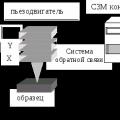 Scanning probe microscope Current state and development of scanning probe microscopy