Connecting an internet cable with wires of different colors. Connectors of laptops and their purpose.
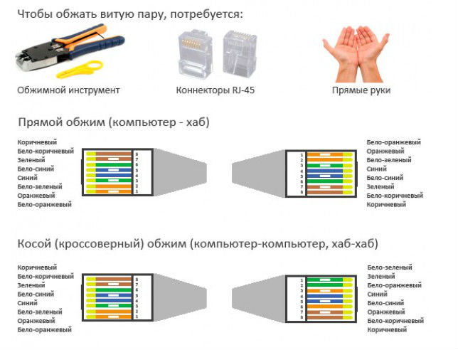
How to crimp twisted pair RJ-45 - 8P8C (rg45, rg 45 ko45) for network - hub - router or patchcord pinout:
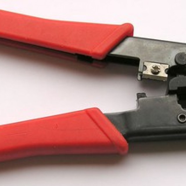
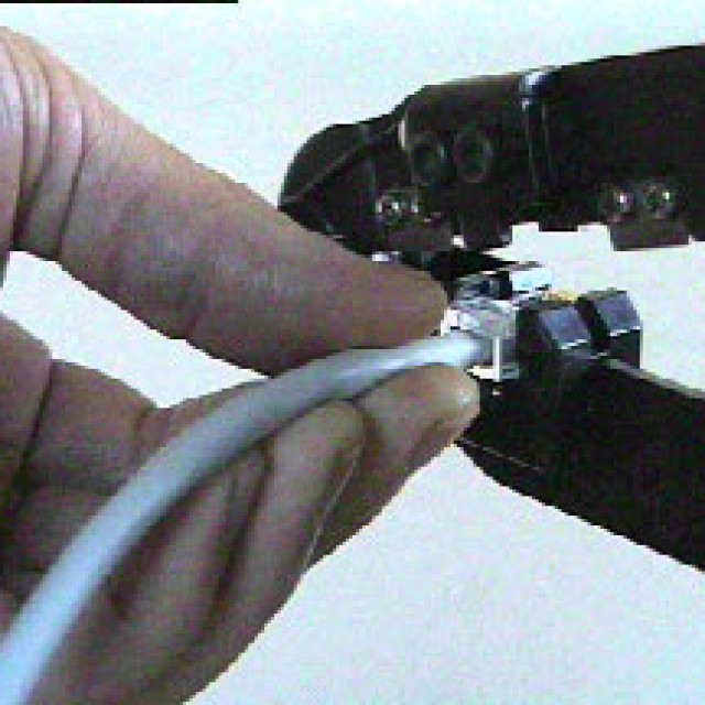
Installation is carried out with a special crimp that presses the metal contacts of the connector pointed from the reverse side into the wire, as a result of which a tight contact is formed. Crimping Rg45 is quite within the power of everyone. In extreme cases, several connectors can be crimped with a screwdriver, with some skill, we will write about this at the very end of this manual, since there are simpler options.
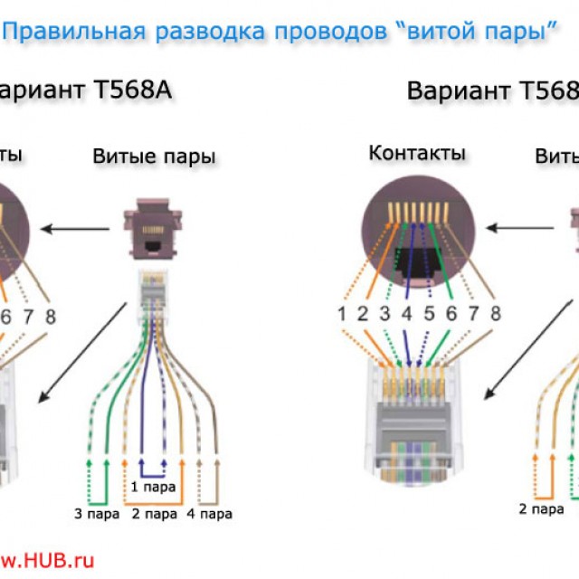
Crimp, RJ-45 pinout by color - color scheme:
B O O B Z S B S Z B K K
White-Orange * Orange * White-Green * Blue * White-Blue * Green * White-Brown * Brown
| Decoding | Pin designation - contact rj45 | |||||||
|---|---|---|---|---|---|---|---|---|
| The most common twisted pair crimping sequence is straight-through: | BO | O | BZ | WITH | BS | Z | BC | TO |
| Twisted pair insulation color | White-Orange-chewy | Orange | White-green | Blue | White-Blue | Green | White-brown-nevy | Brown |
| Pin number RJ45 twisted pair, from left to right, metal contacts to the top - twisted pair to itself - as shown in the photo below | 1 | 2 | 3 | 4 | 5 | 6 | 7 | 8 |
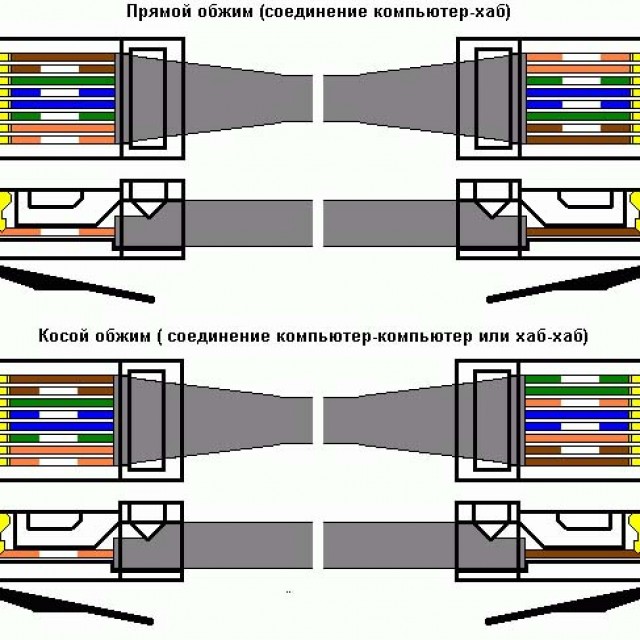
According to the EIA / TIA-568B standard, a computer, TV, receiver - hub, router, stand. We crimp the cable from both ends in the same way as shown in the photo below. One end is a connector Network Card the other is the hub-router socket. The pinout of the patchcord (short wire for rack commutation) is similar.
When using the installation of a computer - network outlet, select the option "B" in the sockets.
Connecting two network cards (computers) directly (without a hub) computer-to-computer, cross-country rj45:
Crossover cable (- crossover Crossover) for connecting two network cards (computers) directly (without a hub) computer-computer at a speed of up to 100 megabits: The white-orange core changes from white-green, orange to green.
B Z Z B O S B S O B K K
On one side, we crimp the wire as shown in the first photo, and on the other side of the wire as shown below. As a result, we will crimp the cable with which you can connect computers directly, without a hub-router, i.e. network card to the network card of computers.
Those. a computer-computer network without a hub router on one side of the wire, the standard above crimp twisted pair, and on the other end of the wire we swap the wires in the following sequence: BZ - Z - BO -S - BS - OR - BK - K.
One twisted pair - one wire - cable for two computers:
Crimping circuit for twisted pair 4 wires. Usually used when it is difficult to pull the second cable. This crimping scheme - wiring the cross cable - is suitable for a 100-megabit connection, since when using a 100-megabit connection, only 2 of 4 pairs are involved, namely orange-b / orange and green-b / green.
If it is impossible to lay an additional twisted pair cable or just for austerity, unused ones are often used - blue and brown pairs, in this case, as already mentioned, you can do with one cable for two computers.
Crimping cable for gigabit network
When using a gigabit connection, all 4 pairs of conductors are already used. In this case, crimping the cable at one end is done as in the first photo, and at the second it takes the form: BZ Z BO K BK O BS S
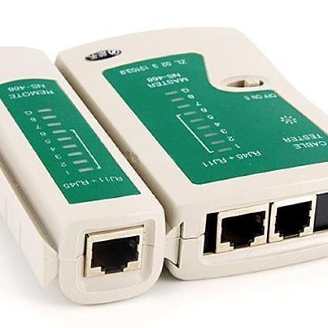
After any crimping, it is advisable to ring the contact with a test device (a special device that sequentially checks all the lines of the wire), and if it is absent, if clearly necessary, with a multimeter.
Crimping RJ 45 with a screwdriver or what to do when crimping is not at hand?
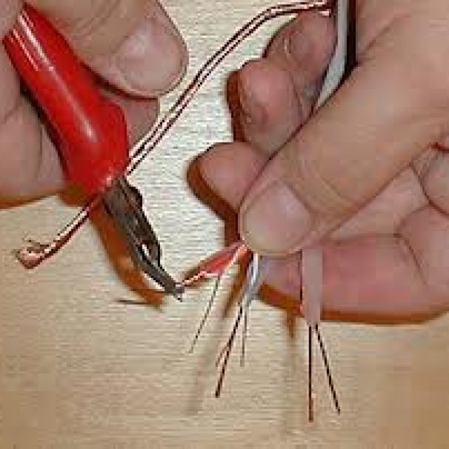
Now let's return to the hopeless situation when the crimp is not available. And to do - to restore the network is necessary here and now. That is, crimp the rg45 with a screwdriver in case of typos (rg45? Ko-45, to 45, to45). So, we take a stock of connectors, and, as always, with a margin of length, a twisted pair. Then carefully cut the wire evenly with small pliers and / or side cutters and / or just with a sharp knife, avoiding any strong flattening. Then, with a margin, we sand the upper braid of the twisted pair. Then we untwist and smooth it in a row according to the scheme given above in terms of wiring colors. If you sanded the wire with too much margin or the ends of the cut are simply flattened, for example, we trim them evenly on a wooden board with a sharp knife. Then we insert as shown in the figure.
So that the metal vein is clearly visible and rests against the very end of the connector and is viewed from the side - if you look at the picture, then from the top side. Then, with a small, sharp enough screwdriver, carefully press down the metal contacts of the connector so that it would be from the side - in the figure above we clearly saw that each connector broke through the braid of the wire, the only thing you need to do is of course not to overdo it, since a strongly deformed contact pad in the connector is also not good.
Then, with a wide screwdriver, press down the transverse plastic with a strong pressure (a hole across the contacts on the connector) so that it bends across the wires to the bottom and squeezes them tightly. If the wire is temporary or often does not move, then this plastic does not need to be pressed. She simply additionally fixes the wiring in the connector. Then, if possible, test it.
Of course, crimping with a screwdriver is not good in every sense, both in terms of efficiency, and in time, and even more so in the quality of the result. Although, in general, it is quite workable (not once personally tested) and a fairly simple option to implement. But it's even easier to just ask a friend who works in the computer - computer sphere to compress 4-6 short ends of the twisted pair and then simply bring them home according to the colors to solder - lengthen the twisted pair.
Of course, not every twisted pair is more or less normally soldered in principle. But acetylenic acid and / or normal soldering acid and / or normal rosin make the impossible - possible. Solder has virtually no effect on speed and stability under normal standard operating conditions.
Twisted-pair cable conductor connection standard:
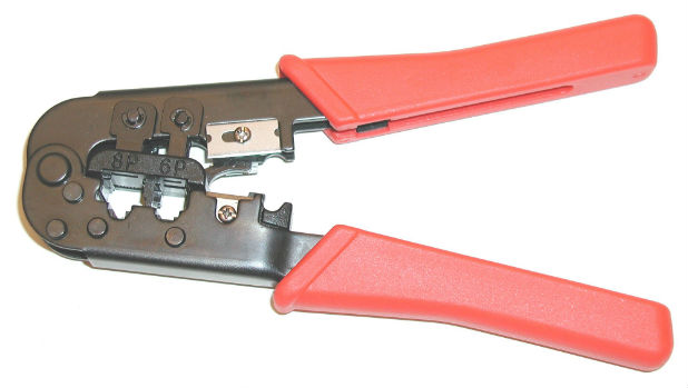
Modern crimps are quite a universal device, in particular, the instructions for the crimping tool shown in the photo above say: For cuts, strips and crimps 8P8C / RJ-45, 6P6C / RJ-12, 6P4C / RJ-11 in one tool. In general, 3 in 1 - trim, unlace and indentation - crimp.
TIA / EIA-568-B (AT&T 258A) is a set of three telecommunications standards released by the United States Telecommunications Industry Association in 2001, which replaces the outdated TIA / EIA-568-A standard. These standards describe the construction of telecommunications structured cabling systems in buildings.
These standards are best known from two tables T568A and T568B (most commonly used in Russia -B), which describe the connection of conductors of a twisted pair cable with the contacts of 8P8C connectors (often mistakenly called RJ-45) when organizing an Ethernet network.
Pin / Ethernet / TIA / EIA-568-B (AT&T 258A)
1) / Transmit + / White with Orange stripe
2) / Transmit + / Orange
3) / Receive + / White with Green stripe
4)
5)
6) / Receive - / Green
7)
8)
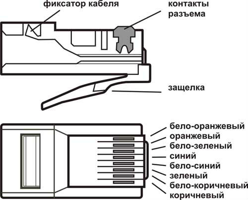
8P8C (8 Position 8 Contact), often due to the prevalence of the above wiring, called RJ45 or RJ-45 - a unified connector used in telecommunications, has 8 contacts and a latch.
RJ - registered jack- any connector used for connections, RJ is a slang name for a modular socket. The abbreviation RJ is used to identify cabling. Each connector type can be used for a variety of wiring configurations. For example, 6-pin connectors are configured as needed for both single pair RJ11C and two pair RJ14C.
It is used to create a LAN using 10BASE-T, 100BASE-T and 1000BASE-TX technologies using 4-pair twisted pair cables. Used in many other areas and for building other networks.
The telephone unified RJ-11 connector is smaller and can be inserted into 8P8C jacks (for backward compatibility).
Types of cable:
Depending on the availability of protection - an electrically grounded copper braid or aluminum foil around twisted pairs, the types of this technology are determined:
* Unprotected twisted pair ( UTP- Unshielded twisted pair) - absent protective shield around a single pair, most often it is UTP category 5 and higher;
* Foil twisted pair ( FTP- Foiled twisted pair) - also known as F / UTP (see: en: Screened fully-shielded twisted pair # Screened Shielded Twisted Pair (S / STP)), there is one common external screen in the form of a foil;
* Protected twisted pair ( STP- Shielded twisted pair) - there is protection in the form of a screen for each pair and a common external screen in the form of a grid;
* Foilshielded twisted pair ( S / FTP- Screened Foiled twisted pair) - an outer screen made of copper braid and each pair in a foil braid;
* Unprotected shielded twisted pair ( SF / UTP- Screened Foiled Unshielded twisted pair) - double outer shield made of copper braid and foil, each twisted pair without protection.
Shielding provides better protection from electromagnetic interference, both external and internal, etc. The screen is connected along its entire length with an uninsulated drain wire, which unites the screen in case of division into sections due to excessive bending or stretching of the cable.
Depending on the structure of the conductors, the cable is used single- and multi-core. In the first case, each wire consists of one copper core, and in the second, of several.
A single-core cable does not imply direct contacts with the connected peripherals. That is, as a rule, it is used for laying in boxes, walls, etc., followed by termination with sockets. This is due to the fact that copper conductors are quite thick and break quickly with frequent bends. However, for "plunging" into the connectors of the socket panels, such conductors are perfect.
In turn, a multi-core cable does not tolerate "cutting" into the connectors of the socket panels (thin cores are cut), but it behaves remarkably when bent and twisted. In addition, stranded wire has a large signal attenuation. Therefore, a multicore cable is used mainly for the manufacture of patchcords (English patchcord) connecting peripherals with sockets.
Using http://ru.wikipedia.org/wiki/Vitaia_pair
If you have any questions - ask- we will help in any way we can (for the comments to work, the included java script in the browser is required):
To comment, just ask a question in the window below, then click "Post as" - type in an e-mail and Name, and click "Post comment".
Typically, this problem is most often encountered by Internet users. One of the common reasons for the lack of access to " world wide web"- inaccurate line switching, when cables literally lie under the computer table and are systematically cut off at the points of connection.
Although it is often necessary to change its routing, while increasing the length. For example, when changing the position of a PC or telephone in a home. In any case, reinstalling (or attaching a new) RJ-45 connector is indispensable. We will figure out how and what can be squeezed at home network cable RJ-45 connector.
general information
The RJ-45 connector is often marked with the "8p8c" symbol. It stands for simple - this connector has 8 contacts and inserts (so-called knives). There are several modifications of this switching element. Depending on the design features, the specificity of its application also differs. RJ-45, which have 3 protrusions, are considered universal. They are used for crimping both single and multi-core cables, which is why all patch cords are made with their help. The connector diagram is shown in the figure.
Required tool
In fact, all you need is a special device for crimping RJ-45 cables - a crimper.
It is inexpensive (in the range of 638 - 689 rubles), and in order not to constantly call the master, it is advisable to purchase, although the crimper does not belong to the class of household tools. In any home there are many places for connecting lines (telephone, computer), which are organized using RJ-45, and this device will definitely be needed more, and more than once.
Sharp sharpened cutting tool. Typically, a scalpel is used to prepare the cable for crimping. It is much more convenient for them to work than with a knife. And the conductor cutting turns out to be more accurate.
Before starting the crimping process, you should make sure that the RJ-45 is suitable for the type of cable you have. Although, this is worth considering when choosing a connector in a store.
Network cable crimping technology
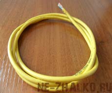
Twisted pair (network cable) is sold in coils. Therefore, it is necessary to lay the cable through the room according to the selected (drawn up) scheme and cut it to length, taking into account a small margin.
A layer of external insulation (by 2.5 ± 0.5 cm) is removed at the end of the cable that is supposed to be crimped. Or with a scalpel, or a miniature knife (found on the crimper itself). It is necessary to perform the work so that the coating of the cores themselves is not damaged. That is why for those who do not have sufficient experience in this area, it is recommended to cut the twisted pair, leaving some margin in length. The explanation is simple - it is not a fact that it will be possible to accurately perform this operation the first time.

The veins are unwound and straightened. If their tips are not aligned, they can be bitten off (with side cutters, millimeter and a half). Otherwise, you will not be able to place them correctly in the RJ-45. The standard by which the connection to the network is made is also taken into account.
Directly crimp. There are two methods - direct and cross (oblique). The first method is realized when the PC is connected to the Internet line. The second - when creating a local network, that is, when connecting two computers.
Operation feature
- When laying conductors in RJ-45, the conductors should not cross, and even more so, should not lie in pairs in 1 socket of the connector - only one at a time. This is typical for their tips, which can twist as they are pressed into the connector housing.
- Before starting crimping, it is recommended to check the wire layout again. That is, to make a control inspection, since it will be impossible to redo something later.
- Installation of a crimper at the place of cable crimping. Then it is simple - to squeeze the handles of the tool. The main thing is not to overdo it.
Checking the line operability. In practice, this is done by connecting the cable to the PC. The result will be clear immediately.
If a patch cord is made (with rj-45 at both ends of a piece of cable), then, in the absence of a special test device, you will have to. To do this, its probes must be sharpened so that they can ensure tight contact with the miniature lamellas of the connector. Further - dialing for each conductor. If everything is in order, you can connect both PCs to each other.
In principle, there is nothing complicated about crimping cables. If you have a crimper, then installing one RJ-45 takes a few minutes.
The cores of the data cable are made of very thin metal wires. That is why it is easy to break them if handled carelessly, by accident. In such situations, you will most likely need to compress it again.
This process is not complicated, but it has its own tricks and nuances. Also, for its implementation, you will need special pliers, but their presence is not necessary - you can carry out the process using an ordinary slotted screwdriver and a clerical knife.
Photo: distribution and termination of twisted pair cable
Before proceeding with crimping the cable, it is imperative to prepare everything you need. And also make sure that you purchased exactly the connectors that are required in your particular case. Connectors are the most different types, the RJ-45 type is usually required to connect the computer to the network.
Varieties of cable
There are many different types of cables used to create a network between different computers as well as networking equipment.
The most common today are three types of communication cables:
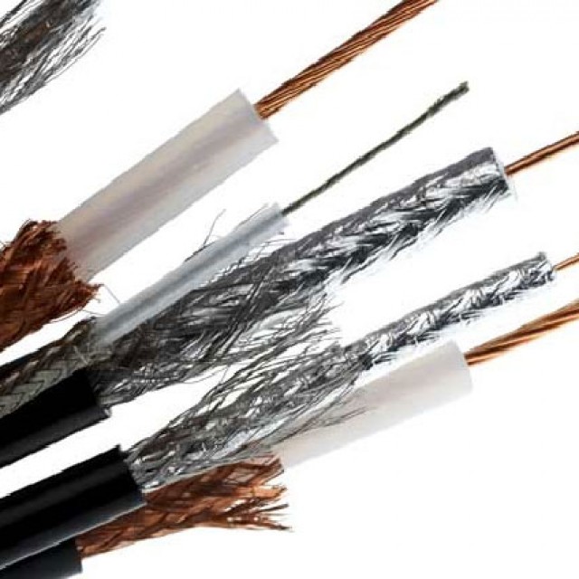
Coaxial was the first to be used to build local networks of various kinds.
It is quite easy to crimp this kind of Internet cable at home; it does not even require a specialized tool - an ordinary clerical knife and a screwdriver are enough. This is where the benefits end.
This wire consists of three main parts:
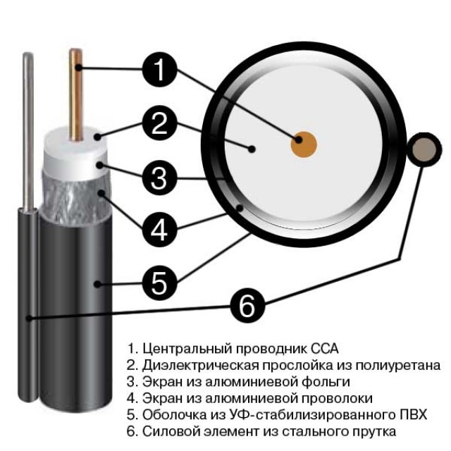
The data transfer rate with this cable is only 10 Mbps. It is extremely susceptible to various kinds of electromagnetic interference; repairing damage to this type of wire is very difficult and problematic. Today it is practically not used anywhere.
Fiber optic (Optic Fiber) is the most modern way to transfer data today.
It consists of the following components:
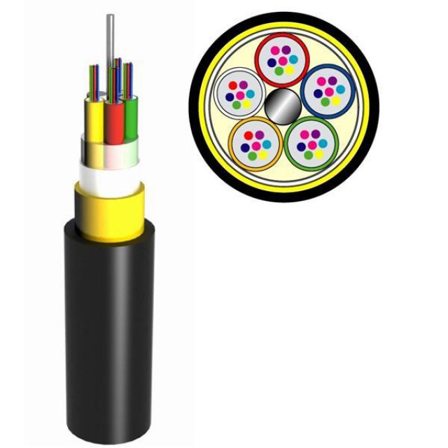
Fiber optic is not susceptible to any kind of interference, the data transfer rate with its help is 2 Gbps. The distance between the individual nodes that this type of wire connects can reach 100 km. There is only one drawback - the rather high cost.
Twisted Pair (twisted pair) - most often, it is used both for building local networks and for connecting to the Internet.
It consists of the following components:
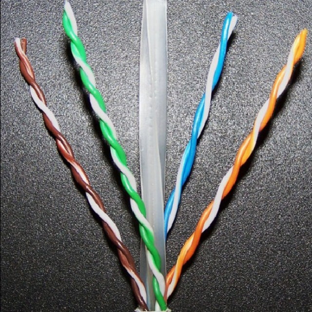
It can provide a relatively high data transfer rate - from 10 Mbps to 1 Gbps.
Twisted pair can be:

Twisted pair is not susceptible to various kinds of interference, it is easily repaired. Correctly crimping a wire for this type of Internet is quite simple, but a special tool is required - a crimp.
Video: Twisted Pair Installation
Installation diagrams
The twisted pair wiring diagram is the order of the cores by color. Another name is pinout.
The most commonly used today are the following types of pinouts:
The pins are numbered from left to right when the copper conductors are on top and the connector itself is turned towards the front towards the user.
Each type of wiring diagram has its own purpose. First type circuit STRAIGHT-THROUGHT(also labeled as T568) is designed to connect end equipment (personal PC, printer) with any switching equipment (router, hub).
Crossover is used when there is a need to connect two pieces of network equipment - a router, a computer.
Straight-through
Straight-through can be implemented in two ways - there are two standards:
The first option is generally accepted, but there are situations in which only the second can be implemented.
Color order when using 568 A:
| Colour | № | Colour | ||
| white-green | 1 | white-green | ||
| green | 2 | green | ||
| yellow-white | 3 | yellow-white | ||
| blue | 4 | |||
| 5 | white-blue | 5 |
white-blue |
|
| 6 | yellow | 6 | ||
| 7 | white-brown | 7 |
white-brown |
|
| 8 | Brown | 8 |
Brown |
|
Color order when using 568 B:
| Colour | № |
Colour |
||
| white-yellow | 1 | white-yellow | ||
| yellow | 2 | yellow | ||
| white-green | 3 | white-green | ||
| blue | 4 | blue | ||
| white-blue | 5 |
white-blue |
||
| 6 | green | 6 | ||
| 7 | white-brown | 7 |
white-brown |
|
| 8 | Brown | 8 |
brown |
|
Cross-over Cross-Over
The Cross-Over scheme is more complex in terms of color coding - their order is somewhat confusing.
There are also two standards, they differ depending on the network bandwidth:
The standard for a 100 megabit network has the following color order:
|
Number |
Colour | Number |
Colour |
|
| white-yellow | 1 | white-green | ||
| yellow | 2 | green | ||
| white-green | 3 | white-yellow | ||
| blue | 4 | blue | ||
| 5 | white-blue | 5 |
white-blue |
|
| 6 | green | 6 | ||
| 7 | white-brown | 7 |
white-brown |
|
| 8 | Brown | 8 |
Brown |
|
The standard of the second type - for a network with a given transmission rate of 1 Gbps - requires the pinout of the wire as follows:
| №1 | №2 | |||
| Number | Colour | Number | Colour | |
| 1 | white-yellow | 1 | white-green | |
| 2 | yellow | 2 | green | |
| 3 | white-green | 3 | white-yellow | |
| 4 | blue | 4 | white-brown | |
| 5 | white-blue | 5 | Brown | |
| 6 | green | 6 | yellow | |
| 7 | white-brown | 7 | blue | |
| 8 | Brown | 8 | white-blue | |
Today, almost all network devices are able to recognize the connection method on their own (have a function called Auto-MDIX). But there is a fairly large number of equipment still in operation that does not know how to do this.
How to crimp an Internet cable with your own hands
It is quite simple to pinout the communication wire with your own hands. This requires only a few items, you can find and purchase them in the nearest computer store... You also need to know the parameters of your network equipment that needs to be connected. Since the crimp type (straight or cross) is selected depending on whether Auto-MDIX is supported.
Tools and accessories
To manually crimp a twisted pair of eight conductors, the following tools are required:
Also, in addition to the tool itself, it is advisable to stock up on several connectors in case the first attempt is unsuccessful.
The order of the work
The process itself is nothing complicated, it is only important to follow the procedure:
When all of the above operations are completed, it is necessary to perform a pressure test. This can be done both with the help of special pliers and with the help of an ordinary slotted screwdriver.
Cable check
It is quite easy to check the crimped twisted pair using a multimeter set to the dial mode. It is necessary to connect the cores by color with contact probes - they should all ring well. If sound signal is not audible, you should press the connector contacts - they are not tightly pressed against the copper conductors.
You can also check the connection using a special device. It checks the strength of the transmitted signal - accordingly, this device will make it easy to find a low-quality pinout.
When working with a twisted pair cable, it is necessary to follow some rules, they will make it possible to avoid communication problems in the future:
Crimping a twisted pair using pliers or even a slotted screwdriver is not a complicated process. It is only important to follow the technology and do everything as carefully as possible. Since a high-quality compressed twisted pair is a guarantee of high data transfer speed. Therefore, before calling a specialist and paying him money, you should try to perform this simple operation yourself.
Today, stranded twisted pair is the most popular and reliable way to transfer information over the Internet or LAN.
Egor Emelyanov,
November 17, 2009, 11:00
Computer technologies have presented the world with new, hitherto unseen opportunities. And the devices that we use to process information have become an integral part of these capabilities: computers and laptops equipped with a large variety of connectors. In this article, we will try to explain in an accessible way the purpose of the various connectors that you often see on laptops.
For ease of reading, we have divided the connector information into five groups:
Universal connectors
USB
The USB (Universal Serial Bus) bus is ubiquitous. This success has been and is facilitated by the high throughput, compactness and durability of the connector, hot-pluggability, versatility and scalability.
Technology
USB was born in November 1995, when the first version of USB 1.0 was launched. This version was practically not used, but its characteristics formed the basis of the mass standard. USB 1.1, devoid of some errors and "childhood diseases" of the original version of the standard.
The USB 1.0 / 1.1 specifications are as follows:
- High-bandwidth mode (Full-Speed): 12 Mbps
- Low-Speed Mode: 1.5 Mbps
- Hot plugging of devices "on the fly" (Hot Swap)
- Maximum cable length: up to 5 m
- Maximum number of connected devices: up to 127
- Ability to connect devices with different bandwidths to one USB controller
- Supply voltage USB devices: 5V
- Maximum bus current: 500 mA
Now used USB version 2.0 whose specification was released in April 2000. The main innovation of version two-zero is the introduction of a new Hi-Speed mode, providing bandwidth up to 480 Mbps.
At the moment, a new, third version of USB is being developed and has already been announced, which has received the corresponding name. USB 3.0... The speed parameters of USB 3.0 exceed those of USB 2.0 by about 10 times and amount to 4.8-5.0 Gb / s. The mass adoption of USB 3.0 is expected to begin in 2010.
The USB connector is easy to recognize - it is a rectangular hole, about 12x5 mm in size, with a "tongue" inside.
A pair of Powered USB connectors on a laptop
The rectangular connector shown in the photo is called USB type A, it is used on laptops and desktops and all USB devices and cables are designed for it.
Connector on type A cable.
The same connector is provided for external USB devices connected to a laptop.
However, on external devices that are connected to the laptop with a cable, the Type A connector is not used; Either type B connector or mini USB and micro USB varieties are used.
Type B connector on the other end of the cable
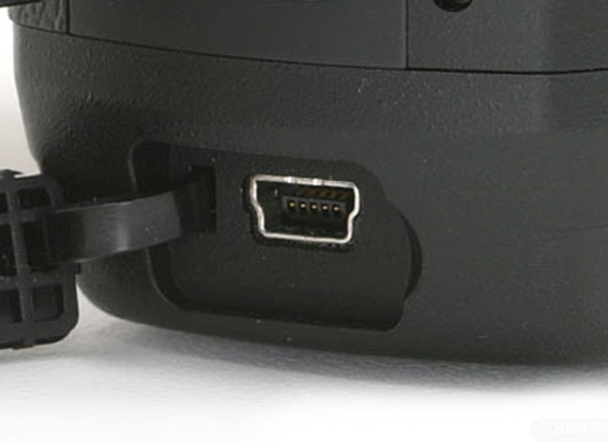
Mini USB connector on an external device
Typically type B connectors are used on printers, scanners, and external drives; port miniUSB equipped with communicators, miniature hard drives, some cameras, USB hubs, card readers; varieties microUSB can be found on some mp3 players and cameras.
Laptops in most cases are equipped with one to four USB connectors. Only occasionally, and on powerful or professional models, there can be more connectors. However, a small number of connectors is not a problem, because the advantage of USB is scalability: multiple devices can be connected to one connector. For this, splitters are used, often called USB hubs (from English USBHub), which can be a stand-alone device or built into a monitor or keyboard, or a laptop cooling pad.
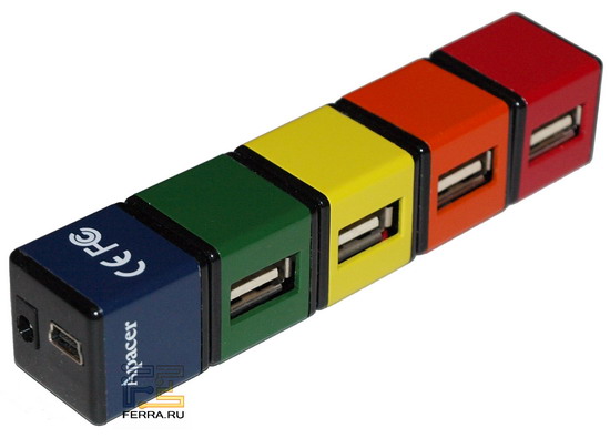
USB hub
To connect devices with a sufficiently high power consumption (such as, for example, external hard drives), the splitter can be equipped with an external power supply unit from the 220 V network, such a hub is called active.
In addition, many compact and professional models mobile computers can be equipped with docking stations (purchased separately), which have additional USB ports.
Important information
- In addition to the above USB versions, there is an option USBOn-The-Go, which has some functionality expansion compared to USB 2.0, which makes USB On-The-Go more versatile and suitable for connecting various devices without using personal computer... For example, USB OTG is used to connect cameras and printers for direct photo printing.
- WirelessUSB, the specifications of which have been known since 2005, allows you to create wireless network based on USB signals (protocol) for connecting external devices. At the same time, the data transfer rate is 480 Mbit / s at a distance of up to 3 meters and up to 110 Mbit / s at a distance of 10 m. The only disadvantage of Wireless USB can be considered the lack of a power bus for devices, which will still require the use of wires.
- Standard USB port according to the specification, it is designed for the consumption of 2.5 W of electricity by the device connected to it (5 V and 500 mA per port). However, modern laptops are capable of delivering more current - up to 1000 mA per port and above. Ports capable of delivering 5W or more are called PoweredUSB, and in the designation of such a port on a laptop case, there is often (but not always) a "+" sign.
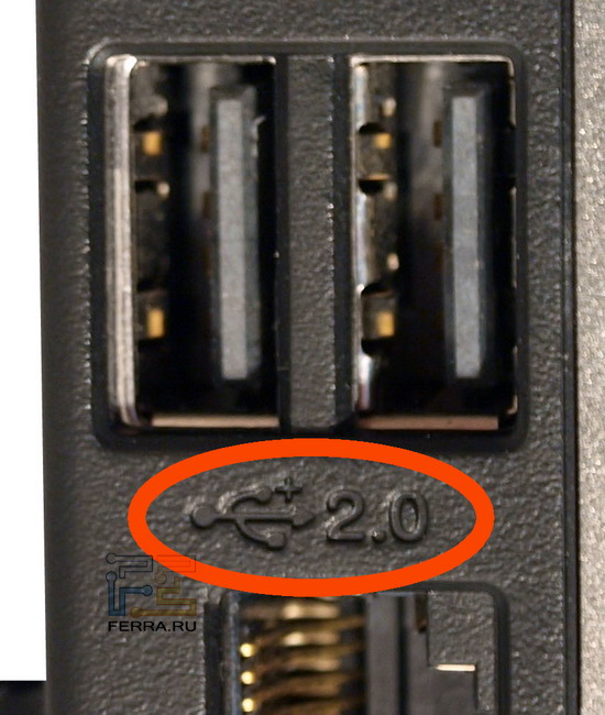
Powered USB port designation
USB Application:
- Connection external storage HDD and Flash
- Connecting phones and modems
- Multimedia connection (TV tuner, sound card, webcam, photo, audio)
- Connecting external video interfaces
- Working with peripheral devices
- Connecting other non-specific devices
Firewire
A type of serial bus used to connect a computer and peripheral devices. The difference from USB lies in slightly less functionality of FireWire and a completely different protocol for exchanging information for FireWire devices. This type of bus allows two computers to be connected to local area network, which does not allow USB to do.
Technology
The IEEE 1394 standard, known as FireWire (Apple), i.Link (Sony, JVC), mLAN (Yamaha), Lynx (Texas Instruments), DV (Panasonic), was created in 1995, just like USB, but the development of FireWire began much before USB - in 1986. Developed by Apple, she also owns all patents.
The advantages of FireWire are:
- Hot Swap Capability
- Flexibility (many devices can work in conjunction without a PC)
- High speed - different versions standard have bandwidth from 100 to 800 Mbit / s, and new versions of IEEE 1394b - up to 3200 Mbit / s
- Open architecture
- Bus powered, and what is important - high power (8-40 V to 1.5 A)
- Connect up to 63 devices to one port (2x less than USB)
A total of 5 IEEE 1394 specifications have been adopted to date.
- IEEE 1394 was originally created for video transmission, as a high-speed serial interface, and was favorably received by manufacturers of external storage devices due to the high data transfer rate: from 100 to 400 Mbit / s at a distance of up to 4.5 m via cable
- IEEE 1394a approved in 2000, technically no different from the previous standard, improved compatibility with various devices, reduced latency when connecting (bus reset)
- IEEE 1394b appeared in 2002. The main differences are the increased transmission speed: S800 - up to 800 Mbps, S1600 - up to 1600 Mbps. To achieve higher speeds, optical conductors are used, but at the same time, compatibility with old IEEE 1394 devices is preserved. In 2007, a new high-speed protocol was adopted - S3200 with the corresponding speed
- IEEE 1394.1 differs from all of the above in the ability to connect a huge number of devices: 64500.
- IEEE 1394c released in 2006 uses standard RJ-45 connectors and Category 5 twisted pair cables. Designed for easy construction of computer networks and can work together with standard LAN protocols, complementing them
The FireWire bus is mainly used to connect external drives, MIniDV / DV camcorders (and other multimedia devices), printers, scanners, and create a computer network.
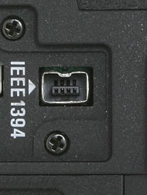
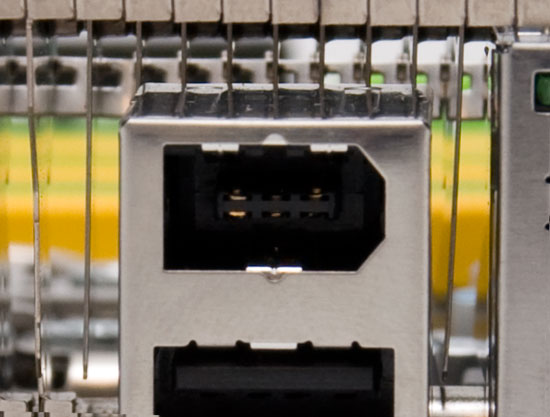
Varieties of FireWire connectors
The advantages of FireWire in comparison with USB can be considered greater efficiency, because the bus retains the signal much more stable. FireWire quite realistically reaches the stated maximum speed 400 Mbps. As a result, it is very beneficial to use external hard drives with FireWire interface.
FireWire's power parameters are also much better - the maximum bus current is 1.5 A versus 0.5 A for USB, with a voltage reaching 40 V. True, power is provided only by a six-pin connector, while laptops are almost always equipped with compact 4-pin FireWire ports designed for connecting devices with external power supply.
The FireWire connector is not present on all laptops, unlike USB. "Why didn't FireWire, with all its advantages, become widespread?" - you ask. The answer is simple: if USB is an open standard, then FireWire is closed; any manufacturer using FireWire in their devices must provide Apple with a certain amount.
FireWire Application:
- External HDDs
- Working with DV / MiniDV camcorders
- Connecting external devices (such as scanners)
- Creation of a local network
Internet connectors
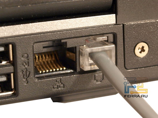
RJ45
LAN port to which you can connect the corresponding leased line patch cord and enjoy fast internet. Despite the development wireless technologies like Wi-Fi or Bluetooth, wired LAN or Ethernet can boast more stable and faster performance, and therefore are still relevant today.
Technology
RJ45 (RJ - Registered Jack) is an erroneous name for the 8P8C type connector (8 pins, 8 conductors). It stuck and is used by most IT authors and publications due to the external similarity of these connectors. In reality, the name RJ45 belongs to the 8P2C connector (8 pins, 2 conductors).
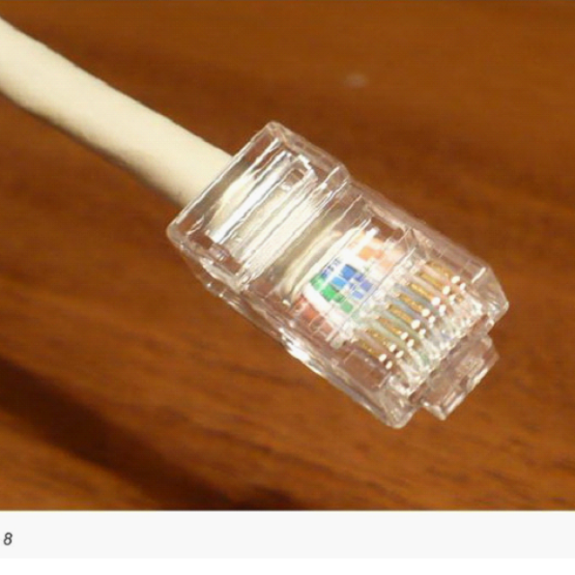
The appearance of the RJ45 connector (we will call it in the usual way) is easily recognizable: it is a rectangular hole with eight spring-loaded contacts inside, on the top of the connector there is a cutout for a latch located on the plug of the network cable.
The speed indicators, which the built-in network controllers of most laptops can boast, correspond to 10/100 Mbit / s, but many modern models are equipped with a high-speed Gigabit Ethernet controller with transfer rates up to 1000 Mbit / s. Nevertheless, in our country, 1 Gbps networks are still not sufficiently developed even in large cities, because they require expensive and high-quality equipment to implement such a high bandwidth.
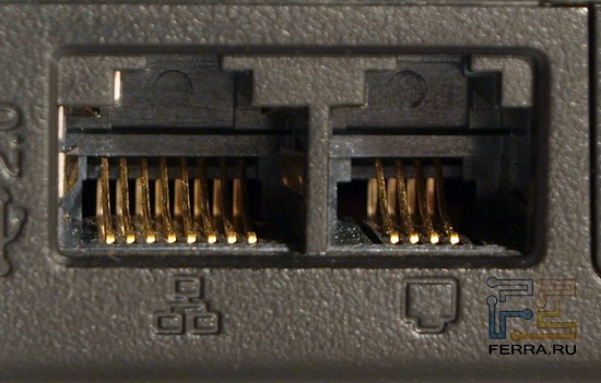
RJ45 for Ethernet and RJ11 for modem
One RJ45 connector is found on any laptop and even a netbook. In general, the approach is justified: there is rarely a need for more than one LAN connector on a laptop. But if suddenly you need a second RJ45 port, then you can purchase network adapter with USB interface, or with a PCMCIA or Express Card slot.
RJ45 Application:
- Connecting a laptop to a dedicated line
- Connecting two or more computers to a common network
- Working with wireless equipment (access points)
- Using Network Attached Storage (NAS)
RJ11
The RJ11 connector is familiar to anyone: any wired telephone has such ports. Externally, the connector is similar to RJ45, only a little narrower. As you might guess, RJ11 is for connecting a laptop to telephone line to access the Network using the built-in laptop modem. There are still many places in our country where good old Dial-Up is the only chance to get online. It only remains to make sure that the PBX to which you are going to connect is not digital, otherwise you can break the built-in modem.
RJ11 connector and telephone cable
RJ11 Application:
- Using the telephone line to access the Internet
- Using your computer as a phone with a headset
- Functionality of a fax machine with a printer and scanner
Discuss on the forum
Hello ladies and gentlemen. Glad to see you at site! This article will teach everyone to how to crimp a network cable... This skill can be needed anywhere and anytime, so I advise you to carefully refer to the material below, especially since the process itself is not complicated.
Crimping a network cable is nothing more than connecting the wires of a network cable to the contacts of an RJ-45 connector in a specific sequence.
RJ-45 connectors (or, as they are affectionately called, "mushrooms" - in the first letters) are a very cheap thing, so buying them in any computer store will not be a problem (the approximate price is 3-5 rubles).
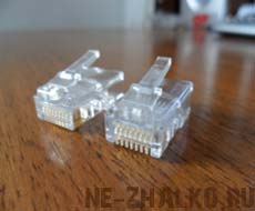
To crimp 1 cable, you need 2 "saffron milk caps", but this is ideally, sometimes a fastening stop or something else breaks off the connector, in this case it is better to stock up on an additional copy.
In addition to connectors for crimping the network cable, you need a special tool (press pliers):

(click to enlarge)
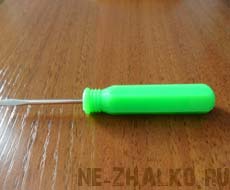
however, you can easily do without a thin flat screwdriver and a small hammer.
If you act carefully, then no one will notice any differences in the crimp.
How the new RJ-45 connector looks like can be seen in the figure above (there are 2 of them next to each other), exactly the same we will use to crimp this network cable
I'll make a reservation right away that in the example, crimping is carried out using a simple screwdriver. If you later often have to work with network cables, then it is more expedient to buy special press - pliers (or "crimping", to put it simple language), their price can vary from 300 to 3000 rubles.
So, we have decided on the available tools and consumables, it's time to choose the option network cable crimps... There may be several options, more precisely 3.
1) Computer<-->Hub / Switch
This option is suitable if the computer is connected to the network through the network card of your computer and the Hub / Switch. Consider the sequence of actions:
a) we cut the insulation of the network cable using a knife (special or ordinary kitchen). The ideal length of stripped wires should be 1.2-1.5 cm. Then this will allow the connector to stick to the insulation of the network cable, and not hang out on too long wires. Proceed very carefully, you cannot damage the internal wiring, it is better to take the cable for a break in the place of the intended cut of the insulation and lightly hold it with a knife at the bend. Next, we get rid of the insulation around the entire circumference of the cable in a similar way. You should end up with something like this:
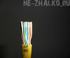
b) untwist, align the internal wiring, then "bite off" them so that they are all strictly the same length. Here such a problem may arise - by cutting off the ends, you can still get wiring of different lengths, so that this does not happen, first straighten the entire piece of network cable (about 30 centimeters from the beginning), only then align the internal wires. For clarity, again, the top figure is suitable.
c) we place the wires for crimping the cable. Difficulties may arise at this stage, since the wires are short and not always obedient. It will help to "warm up" the network cable, directly next to the protruding wires, that is, you can crumple the cable with your fingers, after which the wires can be placed in a slightly different and more suitable way for you. But if the cable insulation is too stiff, then don't be afraid to intertwine the wires to arrange them in the correct sequence. The main thing for us is that they fall under the knives of the connector (metal clamps) in the right order.
Now we insert the wires into the connector channels in the strict order, which is shown below the figure.
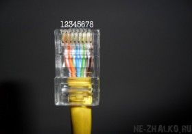
(click to enlarge)
The serial numbers of the wire colors correspond to the channel numbers in the figure:
1 WHITE-ORANGE
2 ORANGE
3 WHITE-GREEN
4 BLUE
5 WHITE-BLUE
6 GREEN
7 WHITE-BROWN
8 BROWN
Let me remind you again - this is the order for creating a Computer - Hub connection. In this order, place the wires at both ends of the network cable.
2) Computer<-->Computer (crossover crimp)
This option involves connecting computers to the local network directly through the network card of one to the network card of the second. The word crossover implies a crossover sequence of wires at different ends of the cable. After reviewing the color order, I think the situation will clear up a little for you. This type of crimp has 2 variations:
2.1 Network speed up to 100 Mbps
First side of the cable:
1 WHITE-ORANGE
2 ORANGE
3 WHITE-GREEN
4 BLUE
5 WHITE-BLUE
6 GREEN
7 WHITE-BROWN
8 BROWN
Second side of the cable:
1 WHITE-GREEN
2 GREEN
3 WHITE-ORANGE
4 BLUE
5 WHITE-BLUE
6 ORANGE
7 WHITE-BROWN
8 BROWN
2.2 Network speed above 100 Mbps
First side:
1 WHITE-ORANGE
2 ORANGE
3 WHITE-GREEN
4 BLUE
5 WHITE-BLUE
6 GREEN
7 WHITE-BROWN
8 BROWN
Second side:
1 WHITE-GREEN
2 GREEN
3 WHITE-ORANGE
4 WHITE-BROWN
5 BROWN
6 ORANGE
7 BLUE
8 WHITE-BLUE
The options for crimping the network cable that I described have been personally tested and work perfectly. Note! If you used a flat-bladed screwdriver to "cut" the connector pins into the wires, do not forget to attach the rj45 connector itself to the network cable. To do this, press in the clip, which is near the bottom of the connector, so that it snaps into place (it can take quite a lot of force). Be careful, otherwise you can damage the connector itself and the mounting stop located just opposite the cable clamp, if this happens, the network cable will fall out of the equipment connector.
As a result of our work, we will get such a perfectly working nice patch - a cord crimped for work "Computer<->Computer "or crossover - type. Although a patch cord is called a factory crimped cable, I still use this term, because the quality turned out to be no worse than the factory
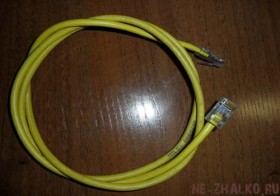
(click to enlarge)
Crossover cables are used for network connection devices of the same type, for example, a network card - a network card or a switch - a switch.
As always, at the end of the article there is an excellent video tutorial on crimping a network cable for different connection options
Everything is pretty easy and understandable, isn't it? Good luck!
 Bugs in Singularity?
 Just Cause 2 crashes
 Terraria won't start, what should I do?