Connecting mini osd to apm pro. OSD for ArduPilot Mega is a system for overlaying telemetry data on flight video. Full Size MinimOSD
Betaflight OSD (Information On Screen) is the integration of information from various sensors into the video stream via the flight controller. Usually the OSD is an additional installed board, or an already integrated chip in the flight controller. OSD transmits information such as battery voltage, horizon, altitude, and more to the helmet or goggle screen.
You can also use the OSD menu to change the quadcopter's PID, filters, and other settings. In this article, I will explain what Betaflight OSD is, what it does, and how to set it up.
Betaflight OSD vs. MinimOSD (MWOSD)
Betaflight OSD is simpler and better than MinimOSD:
- The first is a chip already integrated into the flight controller, you don’t need to solder or connect anything, while MinimOSD is a separate board to which you need to solder all the components of the quadcopter, such as a PC, camera, video transmitter, and so on, depending on which sensors you will use more. In addition, you need a programmer to flash this module through a computer.
- Benefits of Betaflight OSD: Easy setup as everything is already integrated. The configuration takes place in the Betaflight GUI. You do not need to solder, flash anything, you do not need a programmer and third-party module firmware.
- The Betaflight OSD does not occupy a UART port as it is normally connected to the SPI BUS.
Although now MinimOSD is already quite well developed and also has a graphical shell and similar characteristics.
Which flight controllers support Betaflight OSD
Not all flight controllers with an integrated OSD support the Betaflight OSD, some require additional OSD setup software.
Currently, Betaflight OSD is supported by the following aircraft: Matek F405, DYS F4 Pro, Kakute F4, Omnibus F4 and Betaflight F3.
Configuring Betaflight OSD
First make sure you have the latest flight controller firmware as OSD is supported on Betaflight firmware V3.1 and newer.
If your aircraft already has an integrated OSD chip, simply connect the camera and video transmitter to the appropriate ports.
Below is an example of how to connect the camera and transmitter to the DYS F4 Pro FC flight controller, the camera connects to "Vin" and the transmitter to "Vout":
Now connect to Betaflight Configurator, go to the tab Configuration and turn on OSD:
After that, go to the OSD tab to start setting up:
What could be simpler than this interface? Just turn on and off the data you want to display.
Video Format - Select PAL or NTSC, depending on what mode your FPV camera is in. If you don't know what mode the camera is in, set it to AUTO, the program will choose the right format for the camera to work.
Important information: If the preview screen is in PAL or AUTO mode, and your camera is in NTSC, the data shown at the bottom of the screen will be cut off, this is a feature of this format, it has a shorter frame. When using the AUTO format, it is best to place the data you need in the middle of the screen.
In the "Alarm" block, you can set RSSI values, battery capacity, pre-flight time (stopwatch) and altitude. As soon as the data starts to match these numbers, they will begin to flash on the screen of the helmet or goggles.
In the preview window, you can drag the displayed data as you like, but do not put it too close to the edges, because it may then be cut off.
- Battery voltage display
- Flight time (stopwatch)
- Name (own)
- Gas values
- How much current does the drone consume
- How much mAh battery capacity is wasted
To activate the OSD menu in glasses or a helmet, you need a combination of stick movements on the remote control:
- gas in the center
- yaw (yaw, axis roll) left
- pitch (pitch, tilt) forward
The gas must be in the middle of the entire tuning!
To navigate through the menu, use right stick on the remote. To scroll - stick up or down, to select a menu item - stick left / right.
Here you can change PIDs, filters, profiles, and so on. Most of these settings are self-explanatory if you have already configured Betaflight through the OSD tab GUI. But still, not all of the items are here, some are available only in the configurator itself. After you make the settings, go to the main menu and click " Save * Reboot«.
How to change font in Betaflight OSD
If you do not like the font that is shown on the screen, you can easily change it in the Betaflight Configurator, to do this, go to the OSD tab and there will be a Font Manager button at the bottom:
After choosing a new font, the preview window will still show the default font, but you'll have the one you chose with your goggles and helmet, so don't worry.
Frequently asked Questions
Why can't I see data from the OSD in the helmet?
Check if you have specified the correct video format, PAL or NTSC, try swapping. If it still does not work, check the wiring and soldering quality from the camera and transmitter to the OSD module.
How to change the name?
In Betaflight, config tab, scroll down, there will be a text field "Craft name", you can enter another name there.
A special device, Minim OSD, has been developed for users of APM controllers to overlay telemetry data. The abbreviation OSD comes from the English On Screen Display, which means displaying additional information on the operator's screen.
Chinese manufacturers make both flight controllers - HKPliot Mega, ArduFlyer, and OSD controllers - MAVLink-OSD.

Externally, Minim OSD is not much different from MAVLink-OSD, it is like a mirror copy of the board, where the main chip is rotated by 45 degrees. Also, MAVLink-OSD does not have jumpers for selecting the type of video signal and combining the power of the digital and analog parts.
Minim OSD v1.0 had overheating issues when using 12 volt camera power, this issue has been resolved in v1.1.
Due to the fact that HK had delivery problems at the end of 2013, I ordered MAVLink-OSD from RCTimer.

For programming, you will definitely need an FTDI adapter. Therefore, along with MAVLink-OSD, I immediately took the FTDI Tool V1.0 adapter http://www.rctimer.com/product_684.html .

To configure and flash the device, you will need special software called ArduCam-OSD. Download the latest ArduCam-OSD software and firmware here http://code.google.com/p/arducam-osd/downloads/list . At the moment, the current version is 2.0.
You can also install alternative firmware, the project is called minimosd-extra. Information is located here https://code.google.com/p/minimosd-extra/ . For firmware, you will need your own utility - MinimOSD-Extra Config Tool. As a rule, the archive contains a utility and firmware. You can download it here https://code.google.com/p/minimosd-extra/downloads/list . Eyes run up from the number of versions.
I wrapped the board and adapter in shrink wrap.
The controller connector for connection is very inconvenient, six-pin, without “foolproof” protection. All pins are used for programming, but only 4 pins are used to connect to the flight controller.
For programming, it remains to find a mini-USB cable.

As for the four-pin connector, everything is more complicated here. If mixed up and connected incorrectly, then smoke may come out.
Connects the OSD to the flight controller in the telemetry connector. The wire to the OSD must be connected to the central pins: GND, VCC, RX, TX.
If we use a radio modem, then we connect it in parallel. So I had to solder the Y-cable.

The photo shows the wire for the AIOP controller, in which GPS is also connected to one connector.
I did not remove the wire going to the TX of my OSD, so that it would be universal, you never know where I will still use this wire.
It should be noted that if you do not apply 5 volts to the analog part of the board, the board will be silent.

Some resources offer to remake the board and power the analog part from the digital one, but I did not do this, as there is an opinion that interference may appear.
For those who decide to connect from one power source, the circuit will be as shown in the photo.

I currently have the analog part powered by a video transmitter, which I already talked about in my previous article.
ArduCAM OSD Config
Let's start with the native ArduCAM OSD Config utility. At the moment, the current version is 2.1.2.0.
Of the main elements, the program menu should be highlighted, as well as three tabs that switch between the following screens: Config, Panel 1, Panel 2.
Config, everything is very clear here.
First of all, select the port number and click the Read From OSD button.

It should be noted that the type of video signal NTSC - PAL is switched through the menu of the Video Mode program. The File menu item allows you to save and load your settings, or go to the default settings. In the Options menu, you can enable the grid mode for Panel1 and 2, update the firmware, select the background image, use the log for settings, add your own fonts.

Panel 1 is used to customize the information displayed over the video for the first screen. Channel switching is set to a free radio control channel OSD Toggle Channel.

Accordingly, for the second screen, we set up Panel 2.

The firmware is updated using the same utility.

MinimOSD-Extra Config Tool
When we open the MinimOSD-Extra Config Tool program, it seems that we mixed up the folders and launched ArduCAM OSD Config again. This is the first impression, it is actually very similar, but there are more settings.
Let's look at the main differences.
The first item is the choice of model type: Plane, Copter.
Added an option to automatically switch the screen to the one specified in the drop-down menu (Warnings Auto Panel Switch) when a warning occurs. This is necessary when, for example, all information is removed on the second screen so that nothing interferes with the view.
You can choose to display the battery in percent or mA.
And one more Show sign before value block, which is responsible for displaying icons before values.

First screen

Second screen

results
First I installed the firmware via ArduCAM OSD Config.

Everything was normal in principle, but one nuance was disturbing, which was expressed in the following.
After connecting the device, I noticed on the screen that some of the information on the left was cut off. The icons in front of the parameter values are half missing. I decided to try changing the signal type to PAL, as a result it got even worse, it cut off the top and bottom of the screen, so I returned it to NTSC. Let it be only on one side, and not on three, especially since you can try to correct this shortcoming on the left.

Moved information blocks one character to the right.

The operation was painless, there was enough space for this.


As a result, everything worked out, the icons are now fully visible, the information is perfectly readable on the screen.
But MinimOSD-Extra firmware 2.4 R726 was installed, but it began to give out some kind of disgrace on the screen.

The image became unreadable, the information was confused on the entire screen.

Downloaded earlier version 2.2.

With this firmware version, the information began to be displayed without distortion.

conclusions
Compact and inexpensive device. Quite universal, it is used both with the original ArduPilot Mega (APM) boards, and its clones HKPILOT Mega, ArduFlyer, as well as with AIO (All-In-One) series controllers with MPNG or MultyWii firmware. There is information on the forums about connecting to DJI Naza controllers, but this requires work with a soldering iron in your hands.
The only negative is the six-pin connector on the board, into which we connect the cable with the four-pin connector. There can be many variations, if you make a mistake, you can burn the board, since there is no protection.
You also need to remember to power the digital and analog parts of the board, otherwise it will not work. Which method of nutrition to choose, here it will be more convenient for someone.
Of course, I liked MinimOSD-Extra more, as it allows you to perform additional settings that are not in ArduCam OSD Config. But as it turned out, we still need to find a stable version. I came across the fact that with some firmware the output of information over the video is broken. I managed to find a working version not the first time. Therefore, some MinimOSD-Extra options were not available to me. Unfortunately, this is a minus of many open source projects.
Therefore, it is worth noting that ArduCam-OSD Config is more stable and proven.
The controller performs a quality overlay of information on the video, the text looks quite clear and easy to read on a small screen. I did not notice any slowdowns in the display of information.
The OSD is a useful accessory for camera flying. In this article, we'll take a look at what an OSD is, how it connects to our FPV equipment, and, finally, an overview of the capabilities of different OSDs.
If you have any questions - let me know in the comments.
What is OSD and what are its advantages
OSD stands for On Screen Display - i.e. display on the screen or menu on the screen (i.e., on top of the main picture, usually from the camera, some additional information is displayed, mostly text). In our hobby, an OSD is a small printed circuit board that shows flight data on top of your camera image. This allows you to monitor the state of the quadrocopter directly during the flight on the camera.
If you have the right sensors and OSD, you will be able to see flight data right in your goggles or monitor, such as battery voltage, how much current your motors and other electronics draw, your altitude, GPS coordinates, etc.
This makes flying around the camera safer, because you can see the battery level, know when to land, how far you have already flown and in which direction you need to return.
OSD is not required for camera flying, but as you can see it is extremely useful. Most people buy at least a SimpleOSD to see the voltage on the battery, this is necessary in order to avoid overdischarging (if you fly far, then the siren signaling a low battery is not audible).
Data types that can be displayed using OSD
The picture shows the most commonly used data set when flying around the camera.

Timer
Depending on the type of your OSD, this can be flight time (starting from the moment you take off) or operating time (starting from the moment the quadcopter is turned on). Some OSDs allow you to display multiple types of timers.
Battery voltage
Almost all OSDs allow you to display voltage. This is the most important information when flying around the camera, so you know when to land (I usually land when the voltage drops to 3.5V per cell)
Current consumption
If you have a current sensor, then you can track how much current the motors are drawing and how much mAh of your battery has already been spent.
RSSI
RSSI is an indication of the signal strength of your transmitter, usually shown as a percentage. The farther you fly, the weaker the signal will be, this information will help you know at what point you should turn back.
RSSI is the output from your control receiver, usually in PWM format, so you may need a D/A converter and a low pass filter.
Warnings
Some OSDs can display different alarms, warnings, for which you, as a user, must set threshold values for parameters, such as battery voltage, RSSI value, etc.
Airplane mode
Shows the current flight mode of your aircraft. This information will be useful if you often switch between different modes such as Loiter (hovering in place), manual mode, self-leveling mode, so you don't have to wonder what mode the aircraft is currently in. To do this, you will have to connect the flight controller to the OSD.
GPS
Using GPS you get not only the coordinates of the drone, but also its altitude (although it will be more accurate than using a barometer or sonar). Thanks to clever calculations, we can see the speed over the ground, the distance to the starting point and its coordinates (a graphical display of the direction towards the starting point is a very useful thing, especially if you get a little lost).
Horizon
The virtual horizon will help you understand how the drone is tilted in space.
OSD connection in camera, video transmitter and flight controller
I would divide all OSD into 3 types:
- Standalone OSDs
- OSD dependent on the flight controller
- hybrid
Standalone OSDs only connect to the camera and video transmitter, and do not communicate with the flight controller. Sometimes they can be connected directly to GPS or other sensors in order to have access to their readings. A good example of this type is Skylark OSD (+GPS and current sensor) and Super Simple OSD.
Controller dependent OSDs rely only on data from the flight controller, usually via the serial port (RX/TX). The OSD itself does nothing but display this data. The MinimOSD from Hobbyking is a good example of this type of OSD (if the version is unmodified, like KV mod). The advantage of this type is that the OSD uses data received from the sensors of the controller, which means that the controller itself uses this data to simplify management and control. While in the case of standalone OSDs, data from sensors connected to the OSD cannot be used by the flight controller.
The hybrid type OSD can be used as a standalone OSD (with limited functionality), and can also be connected to a controller to increase the set of flight data displayed. MinimOSD with KV mod is a great example of this type of OSD: if used as a standalone, you can see only RSSI and voltage, but when connected to a controller with GPS, then you will see the current flight mode, GPS coordinates, altitude, etc.
Easiest Connection - Standalone OSD
As an example, connect Hobbyking Super Simple OSD to FPV camera, video transmitter and 3S lithium battery.

Theoretically, you can monitor the voltage on the second battery using the Bat2 port.
Connecting hybrid OSDs
I note that in this case, the OSD independently measures the battery voltage and the RSSI level (although it is possible to connect them to the controller and transmit data through its serial port, both options work fine).
If you need to display the coordinates, direction to the starting point and the distance to it, then you need to connect GPS to Naze32.
OSD that I have already used
MinimOSD with KV Team Mod
MinimOSD is currently my favorite OSD and is the one I use. By downloading the appropriate firmware, MinimOSD can be used with Naze32, CC3D, Multiwii, APM and PixHawk boards. This is a very good board that can display absolutely any flight information that is available from the sensors.

MinimOSD can display any information available from sensors
Hobbyking and Banggood sell MinimOSD but they have the original version which doesn't have additional pins on the side for RSSI, battery voltage etc. I would not contact them if it is possible to buy MinimOSD KV Mod.
MinimOSD Micro

Exactly the same OSD as described above, the difference is a smaller size. In addition, there is no 12V -> 5V converter on it, but this is not important, because. anyway, no one uses this converter due to overheating of the board.
BrainFPV
This board also shows anything, with the appropriate sensors.

In the article, we will consider connecting, flashing and configuring MinimOSD. And we will also answer the question of what to do - if something went wrong, and what to do - so that everything does not end sadly.
« Petka - devices!?!? -Three hundred!!! -What's three hundred??? -What about the instruments?
MinimOSD. Cheap and very useful scarf. Allows you to see what is happening now with the copter - the current voltage, how many amperes have been spent, how many global positioning satellites are captured, and also will not let you "get lost" in the sky. It is impossible to get lost in the sky, you say? And here it is very possible. Starting from the elementary “it took off, oh, but everything is different from above ... oh, where am I myself?”, ending with difficult flight conditions, for example, flying in the dark or in precipitation, or accidentally flew into the cloud, as in the video below:
At the fourth minute, only the saving arrow "home" indicated where to fly.
Okay, okay, enough lyrics, let's practice!
PREPARATION.
So, you ordered MinimOSD for yourself. On Banggood or Hobbyking or RCTimer - no matter where, and got something like this:
My hands are itching to connect it to the workstation and see what it shows. But you don't have to do it all at once! It is fraught with ordering a new OSD - and this is lost time (which is the main thing) and of course lost money.
There are two large chips on the board: ATMEGA328P and MAX7456. The first microcircuit (microcontroller, to be more precise) is responsible for communication with the flight controller (the “digital part” of the board). And the second is a single-channel monochrome OSD (OnScreenDisplay - menu on the screen) from Maxim, let's call it the "analog part" of the board. So, this MAX7456 is a rather capricious microcircuit. She does not like overheating, does not like sharp jumps between the "digital" ground and the "analog" - in short, it burns easily. And as luck would have it, the lazy Chinese NEVER solder the regular heat sink of the microcircuit (on the "belly"). If you use a handkerchief in the form in which it came - MAX will burn - 80% guarantee. To prevent this from happening, we solder three holes marked in the photo below.

To do this, insert a thin solder (1 mm in diameter, it is desirable that it be immediately with flux) into the hole and heat it with a soldering iron:

And here is the result (soldering is not very good, but as best I can - you will do better!)

Now about the features of the connection. Attentive people noticed that I soldered the jumper from above. There are several ways to connect MinimOSD, and many copies are broken which is better or more correct or gives less interference. I use the connection method with the combination of digital and analog grounds and power supply from 5 volts from the "digital" part. Since minimOSD consumes quite a lot, it is better to power the board from a separate power source. It almost looks like this:

That is, at the top, I soldered the jumper, thereby uniting the earths. And you still need to drop one jumper, on the "front" side of the board.

CONNECTION AND SETUP
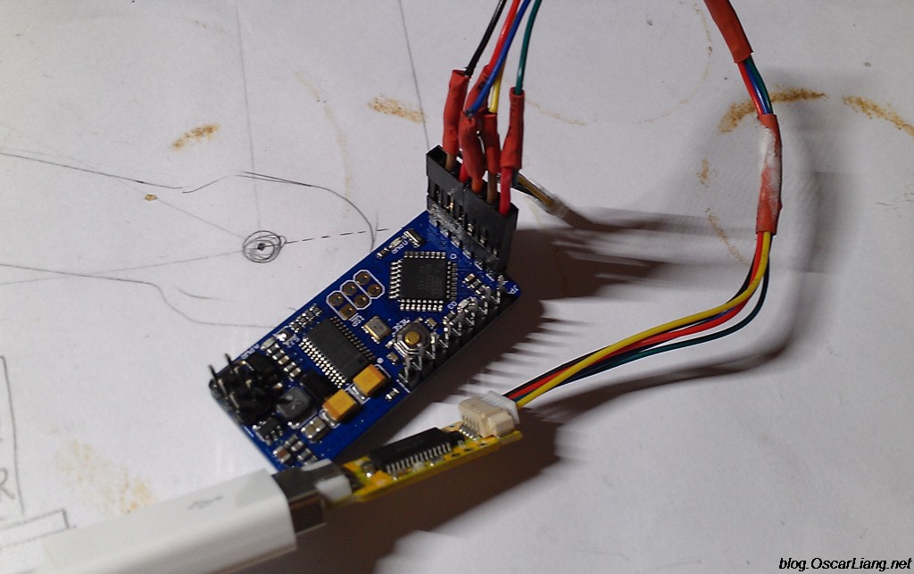
Well, everything is soldered, now our scarf is ready to be connected to the computer. To do this, we need an FTDI adapter (for example, on, or any other USB-UART TTL adapter).

We connect using 5 wires, the connection diagram is as follows: 1. GRN, 2. Tx, 3. Rx, 4. +5V, 5. GND (on the OSD side) - connect them to the FTDI adapter 1. DTR, 2. Rxi, 3 .Txo, 4.VCC, 5.GND. Here's a picture of how it's connected for me:

If it is not clear, watch this video, especially carefully at 1:03
Now, what to download and how to configure. To begin with, I’ll say that for copters and for aircraft, the firmware is different. There is also a firmware for Multivia (kvTeam), and there are also separate mods - from independent work (without a flight controller), to connecting even to Naza.
But here we are considering the "classic" case - a copter on an AWP controller. official page of the project. download page (for a copter under AWP, you need to load ExtraCopter). But these are old versions, people have modified quite a lot since then. Modern firmware are in . At the time of this writing, this is the R800 firmware, it lies (user MinimOSD_Extra, password Top_Secret), on Ya.Disk.
The archive contains the firmware itself (HEX - file), a file with fonts (mcm - file), and the program itself (OSD_Config.exe).
First, let's go to the device manager and check the speed of the FTDI port (we will set 115200):

We launch the OSD_Config.exe program, select the port, press the “Read From OSD” button, there should be a message about successful reading. Since it is not known what firmware is loaded from the factory, so as not to have problems in the future, we will fill it with a fresh one. To do this, click the menu Optios> Update Firmware

select a file and upload it.
We will receive a message about successful firmware

Then the controller will initialize and load the settings into the program, which will be reported

It's time to download the font file that matches the firmware (if this is not done, the appearance of the OSD may turn out to be very funny or even unreadable). Press the menu Option>Update Charset,

select MCM file and upload it

We are waiting for readiness

After pouring, the controller is initialized again.


Let me explain a little:
RSSI channel - converting RSSI into percentages. Where 5 volts is 255 (maximum in octal). And the FRsky receiver has a maximum signal of 3.3 volts. If you check the RSSI enable RAW checkbox, then on the FPV screen we will see “raw” data. It is them that we can drive into the settings. Or you can just type in my values.
Another subtlety - switching OSD screens. As you can see, there are two panels for data. We can switch to three display options - screen1 (Panel1), screen2 (Panel2), blank screen without data (Disabled). To do this, we first need to decide how exactly we will switch between screens. For example, if we switch between screens using a rotary or a three-position toggle switch, then we will have three ranges of values by channels (Panel1: 0-1233, Panel2: 1233-1467, Disabled: 1467-1701). In this case, the Rotation Switching switch must be turned off. And if we switch with a simple two-position toggle switch, then it makes sense to enable Rotation Switching. At the same time, when the toggle switch is on, we will switch screens in turn (Panel1 -> Panel2 -> Disabled -> Panel1 ......), if the toggle switch is turned off, the switching between screens will stop. Which channel will switch screens is determined in the drop-down list entitled OSD Toggle Channel. I put it on channel number 6. And there is another ambush that some (including me) are initially confusing - Warning Auto Panel Switch. This list defines which screen to switch to when any of the previously defined warnings occur. It would seem that everything is clear. You are flying yourself, something happened in flight, the OSD switched to the screen that you asked. But here's the question - we set switching between screens, as a rule, this is configured at home, the copter does not fly, we want to check - the screens do not switch! But because there is usually no GPS Fix at home - in short, a warning worked! So switching between screens “does not work” ... 🙂
I don’t know if the rest of the parameters need clarification, maybe I’ll supplement the article later.
I can only say that when setting up the main screen, you should not shove everything there at once. It’s better to turn everything off first (in the column on the left), and only then turn on only what you need and immediately place it in the right part of the screen. I recommend leaving an empty space at the edges of the screen, it can be cut off by a monitor or DVR with a stylus or glasses.
Next, another important point - OSD setup in Mission Planner. Suppose you have connected everything as it should, but instead of funny numbers and artificial horizon, we see the boring inscription “No Mavlink Data”. This means that the OSD is working, it would be happy to show you something, but it is not receiving data. That is, no data from the workstation comes to the Rx pin. The first possible reason is the wires are mixed up when connecting. Check that the Rx from the OSD is connected to the Tx port on the workstation. The second possible reason is that the controller itself is not configured to send data to the COM port. To do this, in a simple case, on the INITIAL SETUP > Optional Hardware > OSD tab, you need to poke the Enable Telemetry button. At the same time, the MP automatically configures a number of parameters that allow you to send data to the OSD. If this magic button did not help, then you will have to set everything up with little hands. To do this, go to the CONFIG / TUNING > Full Parameter List tab, scroll down to the letter S, and check (or correct) the parameter values:
- SR0_EXT_STAT = 2
- SR0_EXTRA1 = 5
- SR0_EXTRA2 = 2
- SR0_EXTRA3 = 3
- SR0_POSITION = 2
- SR0_RAW_SENS = 2
- SR0_RC_CHAN = 5
If the data is still not coming, and we still see the dull inscription “No Mavlink Data”, then you need to check whether the OSD is connected to the right port (the article talks about UART0), you may need the SR1 parameters (the same as described above, for UART1 port only). It is also possible that the OSD does not work for you along with the telemetry modem - in this case, you may have to connect or, on the contrary, disconnect the Tx wire on the OSD. There is also a glitch that the OSD does not work when the USB cable is connected to the computer. Or maybe you just messed up the wires ...
I'll share one more photo. On my controller, due to a crash, the main port for telemetry stopped working, I just soldered to UART0. And then I liked this connection.

Here I powered directly from the controller. But it is MANDATORY to check what is left of 5 volts to the controller itself. In my case, the controller itself is powered from the receiver, and there it is set to a little higher than 5 volts, so that, taking into account the receiver and minimOSD, for the APM itself it was strictly 5 volts.
One more point needs to be touched upon. If the OSD is flashed incorrectly, the error " failed to talk to bootloader". This error literally translates as "error talking with the bootloader." It can occur either in the case of tangled wires, or when the bootloader crashes. If in the case of wires everything is clear (see above how to connect correctly), then in the case of the bootloader, a procedure for restoring the microcontroller is needed.
Restoring Bootloader.
To do this, we need at least a programmer. It is more convenient to use USBasp.

maybe you will like this adapter (ISP10<>ISP6)
 or this cable (available on)

In general, one way or another, we connect to the ATMega328P using a programmer.
The pinout of the ISP connector on the OSD board is generally accepted. Usually the first contact is square. If not, it's best to verify by looking at Vcc and GND.

On the programmer, the pins are usually signed, if not, then it usually looks like this:

To do this, first select the type of programmer

Then choose the type of board

And microcontroller type


and wait about a minute until the bootloader is loaded (look at the green status bar at the bottom)
 Until a message appears that the bootloader has been successfully flashed

(we do not pay attention to the errors below, you need to update the firmware of the programmer)
Next - go to OSD_Config.exe, fill in the firmware and fonts, as already described. You may have to upload the firmware twice (one more time is needed for the correct initialization of the controller after uploading the bootloader).
Well, that's about all. Suddenly, who does not know, there is more. If something is not clear here, you can "live" see it there.
Good luck with installing OSD on your quad!
Always yours, Ganiev Timur - 5yoda5.
5yoda5#apmcopter
Update 11/11/2015:“Well, everything is soldered, now our scarf is ready to be connected to the computer. To do this, we need an FTDI adapter (for example, on the RCTimer, or any other USB-UART TTL adapter).
Update 11/03/2016: Added ISP pinout images.
If you find an error on the page, then click Shift+Enter or to notify us.
In this guide, we will cover both the regular and Micro versions, how to set up and use the MW-OSD firmware, as well as how to connect to the Naze32 and the receiver.
What is MinimOSD and Micro MinimOSD
Although setup is much more complicated than other OSDs like Super Simple OSD or E-OSD that I plug in and work immediately, MinimOSD has many advantages and the screen appearance is fully customizable.
Most useful features: display of GPS coordinates, customizable styles and fonts, using the on-screen menu, you can change the coefficients of PID controllers, rates, etc. An example of what can be displayed on the screen.
Setting PID coefficients through the menu:

Dimensions, weight, pinout, soldering to reduce dimensions
Full Size MinimOSD
This OSD has been around for many years. The advantage of this version (MinimOSD with KV Mod) is that it has pins on the side for connecting a current sensor, RSSI, voltage sensor, etc. Previously, we had to very carefully solder the wires directly to the legs of the chip ourselves, and this was very difficult. This version has made life a lot easier. I bought myself one such board (version 2)

MinimOSD dimensions with KV Mod V2: width 21mm, length: 43mm, weight: 5.5g (including connectors).
Micro MinimOSD
I'm amazed at the micro size of this OSD, but it has all the features of the full size version. In addition to the possibility of power supply from 12V, which was almost never used in the old version, due to overheating of the board. So it was very reasonable to throw out this functionality and reduce the size.

The micro version is about 1/3 full in weight and size.
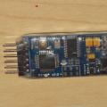
Soldering connectors
Soldering the connectors to the full size MinimOSD was easy and straightforward, but for the micro version, I don't like the way people usually solder them.

My creative is to use angled connectors instead of straight ones so I have extra space when mounting inside the quad.
At the very end, we pack in heat shrink to protect soldering and wires.
Connect to Naze32, battery, receiver, camera, video transmitter
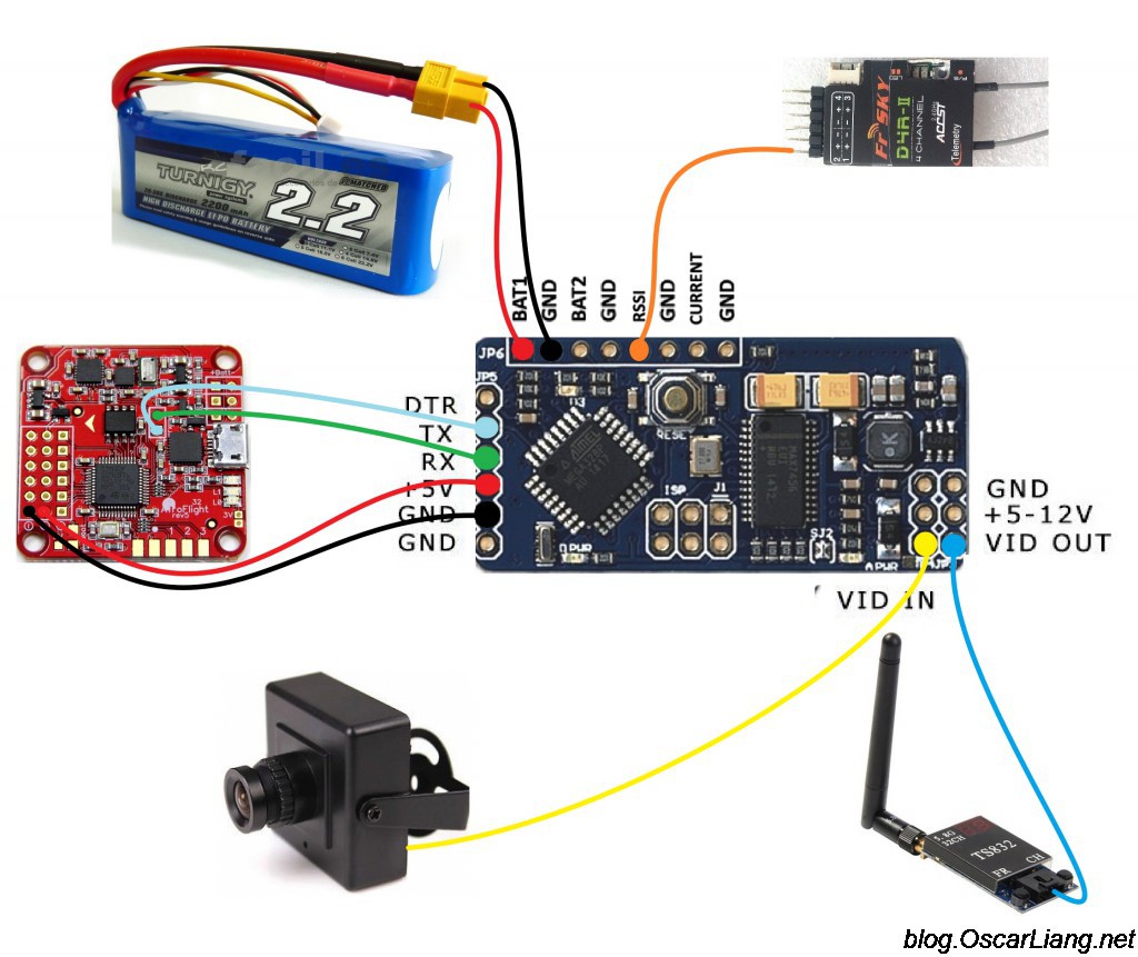
The assembly of my copter is very simple. Here in the diagram everything that needs to be connected: Naze32, LiPo, receiver, FPV camera and video transmitter.

Connection diagram of a regular MinimOSD with Naze32, camera, receiver, video transmitter, battery.
How to connect the micro version:

Frequently Asked Question 1. Some complain that the text disappears when the throttle is increased. Solution: connect all electronics - camera, OSD, video transmitter to a common ground.
FAQ 2. OSD is not displayed, only the picture from the camera. Solution: try changing the PAL/NTSC standard in the OSD settings.
The VBAT1 pin is connected to the main lithium battery to show voltage. The RSSI pin is connected to the control receiver to display the signal level (if the receiver is FrSky D4R-II, in CPPM mode, then Pin1 is the PPM signal, PIN2 is the RSSI output).
Connecting to the Naze32 via the serial port (TX and RX) will allow the Naze32 to send flight data to the screen (GPS, compass heading, etc.) and the OSD will be able to change the PID coefficients of the flight controller using the remote controller.
Be careful! The connection to the computer uses the same serial port, which means that if you want to use Baseflight or Cleanflight configurator, you must first disable TX and RX from the OSD.
Without a serial port connection, the MinimOSD will display RSSI and voltage on its own.
If you are using Taranis in PPM mode, please read this article: how to get RSSI on a separate channel (without additional wires).
This is what it looks like inside my mini quad.
Configuring with MW-OSD GUI
There are quite a few firmwares for MinimOSD, my favorite is Multiwii-OSD (mwosd). The current version is 1.3., its configurator is a very handy program. The on-screen menu is clear, the firmware is updated, there is support for Cleanflight and Baseflight. It also allows you to adjust the PID gains directly from the OSD.
Connect MinimOSD to FTDI programmer
Both setup and firmware require an FTDI adapter. The connection goes through 5 wires: DTR (GRN), TX, RX, 5V and GND.


Setting up MinimOSD using the MW-OSD GUI
Through the graphical interface, you can configure the display of any flight data. Because I'm flying a mini quad, all I need is battery voltage, RSSI and a timer. I'm using 4S lithium batteries and the low battery warning is set to 13.6V (3.4V per cell, though I should set the threshold higher). For the 3S configuration, the voltage at which the warning appears can be set to 11V. I use FPV in PAL format

The only thing to worry about is battery voltage. The default value is far from ideal, so you have to play around with the settings to get the correct value. How do I do it:
The default value for " voltage adjust" = 200, and the voltage displayed by the OSD was 21.0V. I took a multimeter, measured the voltage on the battery, and got 11.1V

Now let's decrease the value voltage adjust“up to 110, now I have 11.5V on the OSD screen. To avoid constant back and forth changes in the parameter, we must calculate the exact value using math and the information we already have 🙂 We must calculate how many volts gives 1 value of the "voltage adjust" parameter.
(21.0-11.5)/(200-110) = 9.5/90 = 0.1056
We know that the correct value on the screen should be 11.1V, so the value " voltage adjust"should be:
110 - (11.5-11.1) / 0.1056 = 106.21 (106 is fine)
Meaning " voltage adjust» can be changed not only in the configurator, but also through the on-screen menu, so there is no need to connect MinimOSD to the computer and use the configurator.
Arduino as programmer for MinimOSD?
I tried using my Arduino UNO as an FTDI programmer, as I have done for other devices before. I managed to change the OSD parameters through the MW-OSD GUI program. However, I ran into a problem when flashing MinimOSD, the error message was:
avrdude: stk500_getsync(): not in sync: resp=0x00.
It looks like some kind of data sync issue, but I made sure I connected the DTR to RESET on the Arduino properly, I don't know what else to do, so I used my FTDI programmer to flash the MinimOSD.
OSD Menu: Set up PIDs, Rate, Voltage, RSSI
The OSD Menu is my favorite feature, and that's basically why I've given up SuperSimple OSD. There are a lot of settings that you can change without connecting to a computer. For example, I can change the values of the PID coefficients directly in the field using my remote control, without bluetooth and a computer! However, you cannot change the roll rate and pitch rate parameters separately in Cleanflight (English), at the moment they are linked (you can only change both at once, approx. Transl.) In the new version, these parameters will be independent.
To get to the MW-OSD menu, you first need to disarm the copter, then:
- gas in the middle
- yaw (yaw) - right
- pitch (pitch) - forward.
To navigate through the menu:
- Roll / pitch (pitch / roll) - to move through the menu
- Yaw (yaw) - to change values
- PID Config (Roll/Pitch/Yaw PID for different flight modes)
- RC Tuning (RC Rate, RC Expo, Pitch/Roll Rate, Yaw Rate, TPA (Throttle PID Att)
- Voltage (show or not voltage, "Adjust Voltage", "Voltage alarm", "Cells" values)
- RSSI (show or not)
- Current (show the consumed current or not, its setting)
- Advanced (Units: Meters/Inches, Signal: Pal or NTSC, Compass)
- Display (switches, throttle, GPS coordinates, sensors, gimbal, etc.)
- Statistics (distance, max. altitude, max speed, flight time)
flashing
Some MinimOSD vendors flash the latest version themselves, so you don't have to worry about flashing. But maybe later you will want to update the firmware or try another one, to check the firmware version, turn on the OSD on the quad, and look at the inscription on the boot screen.
Each firmware in the instructions describes in detail how to flash. This is the summary:
- Download firmware files.
- Download Arduino IDE
- Open firmware files in Arduino IDE
- Change settings if needed
- I did not change much, only the board type (WitespyV1.1) and the flight controller firmware (Cleanflight)
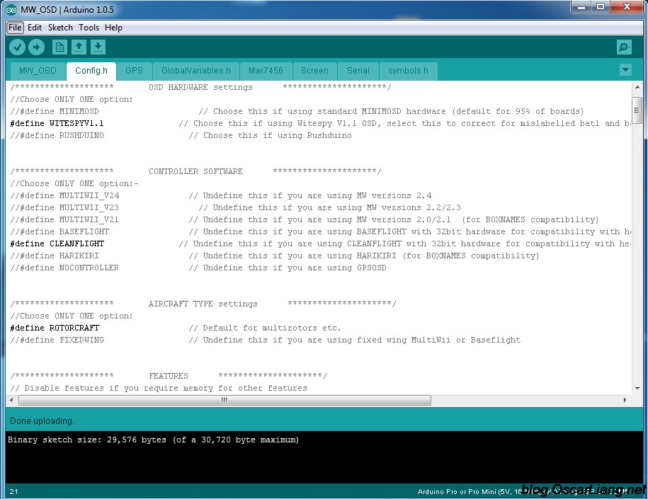
- Connect FTDI adapter (programmer) to MinimOSD / Micro MinimOSD
- Click Compile and Upload
 OSD for ArduPilot Mega - a system for overlaying telemetry data on flight video
 Why won't my Windows PC connect to my phone in Wi-Fi hotspot mode?
 Solving the problem with adjusting the brightness on a laptop