An automatic charger is a must have for every car enthusiast. We make our own chargers for a car battery How does the charger work
Nowadays, every family has a large number of electronic devices in use. Phones, smartphones, flashlights, tablets, toys for children of all ages and many other household appliances need power from portable power sources: batteries or rechargeable batteries.
Power supplies are designed for long-term operation, but can quickly fail due to negligence. In order to make the most of the manufacturer's resource inherent in them, we recommend that you familiarize yourself with the operating features of batteries of various designs, the rules for charging and safe handling.
For the most impatient readers, you can skip straight to the factory recommended charging rules. They are listed at the end. However, consistent reading of the material will allow you to better understand their features and correctly apply them in practice.
How the battery works and works
The entire wide range of battery products operates on a single principle of converting the energy of chemical processes into electrical energy. A special design has been created for its flow.
Battery Principles
A sealed vessel, called a jar, is filled with electrolyte. Two separate plates of different metals, called electrodes, are placed in it. An electrical potential difference is formed on them, which is capable of performing useful work.

To increase the power of energy, cans with plates are made oversized or connected in parallel chains. To raise the output voltage, they are connected in series. Such designs are called rechargeable batteries.
Classification
By type of electrolyte, batteries are divided into:
- liquid;
- gel.
According to their design features, liquid batteries are divided into:
- acidic;
- alkaline;
- saline.
Acid battery designs are relatively rarely used. They can be found in budget models of flashlights, where they work in conjunction with a charger.

Alkaline batteries are generally oversized. Previously, they were used for lighting in portable lamps, but now such structures are not convenient for work and have ceased to be used.

V mobile devices ah for home use, popular battery models:
- lead acid (Pb + H 2 SO 4);
- nickel-cadmium (Ni-Cd);
- nickel-zinc (Ni-Zn);
- nickel metal hydride (Ni-Mh);
- lithium-ion (Li-ion);
- lithium polymer (Li-Pol)
Design features of various models
A typical device of a battery of batteries, consisting of separate cans with a set of positive and negative plates inserted into them, the sequence of their arrangement can be observed using the example of an acid battery.

The designs of the cylindrical or "finger" models are a cutaway view for a lithium-ion battery with explanatory captions for each layer.

Battery appearance
The dimensions and shape of current sources are created for their convenient location in the sockets of mobile devices, reliable power supply to consumers, and the possibility of fast charging.
Batteries can be in the form of a cylinder or a tablet, as shown in the photo for common nickel-cadmium devices, which are assembled into blocks with special jumpers.

When, according to the operating conditions, it is preferable to receive power from a single unit, then a common case is created. Separate finger elements are built into it, which, due to their parallel and series connection, provide output characteristics for current and voltage.
This is the principle behind the creation of laptop batteries.

For small-sized mobile devices, batteries are created in the form of a small parallelepiped with rounded edges. On one of the end sides, it has brass platforms mounted, which ensure the creation of an electrical contact for the source and consumers of current.

The principle of converting chemical energy into electrical energy of interest to us is explained by the picture.

A redox chemical reaction takes place between two adjacent substances with selected properties. It is accompanied by the release of electrons and ions, which, as you know, form an electric current when moving.
For moving charges to create electrical potentials, and not just generate heat into the environment when mixing an oxidizing agent with a reducing agent, it is necessary to create conditions for this.
These purposes are served by:
- anode (positive charge) that carries out an oxidative reaction;
- reducing substance cathode;
- electrolyte, conducting current during the dissociation of the working medium into cations and anions.
The anode and cathode are placed in distant vessels that are connected by a salt bridge. Anions and cations move along it, creating an internal battery circuit. The external circuit is formed by connecting a consumer to an input, for example, a voltmeter or other load.
At the anode and cathode, electrons and ions are constantly being transferred to the electrolyte and vice versa. In the inner chain, charges move through the salt bridge, and in the outer chain, current flows from the anode to the cathode.
This principle is the basis for charging and discharging all models of chemical current sources.
How Nickel Cadmium Battery Works
There are only two types of work:
- discharge;
- charge.
You can also distinguish the storage mode, but it is more correct to class it as a category that they try to limit as much as possible, although it cannot be completely avoided.
Discharge cycle
The energy accumulated on the electrodes, when a load is connected to them, creates an electric current in the external circuit.

Nickel oxides with inclusions of graphite particles, which reduce the total electrical resistance, work as an anode in a nickel-cadmium battery. Spongy cadmium is used as the cathode.
During the discharge, active oxygen molecules are released from the composition of nickel oxides, which enter the electrolyte and further to cadmium, oxidizing it.
Charge cycle
It is customary to carry out it when the load is removed. Then you can use less power of the charger.
The polarity of the terminals of the charger and the battery must match, and the external power must exceed the internal one. Then, under the influence of an external source inside the battery bank, a current is formed with a direction opposite to the discharge.
It reorients the course of chemical processes in the container of the can, enriches the anode with oxygen and reduces cadmium at the cathode.
How does a lithium-ion battery work
A carbon anode and a cathode of metal oxides containing lithium, for example, of the composition LiMn 2 O 4, are immersed in an organic electrolyte.

Positively charged Li + ions move in it. In this case, lithium itself does not pass into a metallic state, but an exchange of its ions between the electrode plates is created. For this reason, batteries are called lithium-ion batteries.
Charge cycle
Lithium ions are removed (deintercalation process) from the lithium-containing cathode and incorporated into the anode (intercalation).
Discharge cycle
The movement of ions goes in the direction opposite to the charge, and the electrons from the anode move to the cathode and form an electric current.
If we compare the principles of operation of a battery of any design, then we can observe the general pattern of movement of ions between the electrodes along the internal circuit and electrons along the external circuit when creating charge and discharge circuits.
Battery performance
Working voltage
Its value is determined at the open terminals with a voltmeter at an optimal charge. In the process of work, it gradually decreases.
Battery capacity
A characteristic showing the amount of current in milliamperes or amperes that a battery can deliver over a period of time, expressed in hours.
Power
A parameter that takes into account the ability of the battery to perform work per unit of time.
How does a mobile device battery charger work?
Now all expensive electronic devices are supplied with their own power and charging devices.

Separate batteries are available to restore the performance of batteries used individually. charging device... They are accompanied by instructions and tables indicating the recommended duration of the technological cycle.

Such models usually provide a stabilized voltage to the terminals of the battery, in which the electrical resistance gradually changes during charging, which affects the amount of current flowing. Therefore, these recommendations are of an average nature.
Forms of currents generated by chargers
To charge batteries, not only direct currents can be used, but also many other types that solve specific problems.

To ensure their flow, various electronic circuits are created that supply a voltage of the appropriate type to the battery terminals.
Schematic diagrams of chargers
In view of their variety, we will give as an example some typical solutions.
Constant current generation circuit
The voltage is reduced due to the transformer. Its harmonic is rectified by a diode bridge and ripple is smoothed out by a high-capacity capacitor.

Constant currents are supplied to the battery output.
The scheme for creating pulsating currents

By removing the capacitor from the previous chain, we obtain voltage ripples at the battery terminals, which form currents of a similar shape.
Scheme for creating pulsating currents with a gap

Replacing the diode bridge with a single diode, we obtain the ripple of currents of increased frequency by a factor of two.
Service chargers
By increasing the complexity of the internal circuitry, various additional functions are created for the chargers. 
In all calculations of the value of the charging current Ic in amperes, an empirical ratio is taken as the base value, measured as a percentage of the value of the capacitance C, expressed in ampere-hours.
However, for certain models, the manufacturer may indicate the charging current immediately in numerical terms in amperes, which does not comply with this rule. It is clear that he has good reasons for this.
Lead acid batteries
It is customary to use currents for charging, amounting to 10% or 0.1 of the capacity C. They are recorded as 1C.
For these batteries, the voltage on a single cell should not exceed 2.3 V, which should be taken into account when charging the battery in order not to exceed the critical value.
The accumulation of the capacity of acid batteries after reaching 90% of the nominal value is exponential. Therefore, further charging is performed with reduced currents with control of the voltage on the banks, which increases the duration of the process.
Lead-acid batteries need to periodically conduct a control training cycle with a full discharge and charge.
Alkaline batteries
For them, it is customary to maintain the charge current at 25% of the capacity or 0.25C.
Nickel-cadmium battery models
The optimum temperature for charging, as well as for work, is within + 10 ÷ 30 ° C. At this temperature, oxygen is better absorbed at the cathode.
Cylindrical accumulators are mounted by tightly wound electrodes into a roll. This makes it possible to effectively charge them with currents within a wide range of 0.1 ÷ 1C. The standard mode provides for currents of 0.1C and a time of 16 hours. At each element, the voltage rises from one to 1.35 V.
If an overcharge control system is installed in the charger, then increased currents of constant form with a value of 0.2 ÷ 0.3C are used. This allows the charging time to be reduced to 6 or 3 hours. Even an overcharge within 120 ÷ 140% is admissible.
A characteristic drawback of nickel-cadmium batteries is the "memory" effect or reversible loss of capacity, which manifests itself in violation of the charging technology, or rather, after the start of recharging a battery with an incompletely used capacity.
The battery “remembers” the limit of the remaining reserve and, upon subsequent discharge to the load, reduces its resource when it is reached. This feature is taken into account during operation, and for storage of Ni-Cd batteries, they are transferred to a full discharge mode.
Nickel Metal Hydride Battery Models
They were created to replace nickel-cadmium batteries, have no memory effect, have increased capacity... But, in preparation for work after a month or more of storage, a full discharge cycle is required, followed by charging. Having completed 3 ÷ 5 such cycles, you can increase the working capacity.
To store these batteries, their capacity is converted to 40% of the nominal value.
Charging is carried out using 0.1C technology for nickel-cadmium batteries, but with temperature control. Its excess over 50 О С is unacceptable. Strong heating occurs at the end of the cycle when the course of chemical reactions slows down.
For these reasons, specialized chargers with built-in temperature sensors are being created for nickel-metal hydride batteries.
Nickel-zinc battery models
The voltage of one can is 1.6 V. The charging current is 0.25C. Charge time 12 hours. There is no memory effect. The recommended limit for reaching capacity when charging is 90% of the nominal.
Do not heat more than 40 ° C. Limited resource - three times shorter than that of nickel-cadmium batteries.
Li-ion battery models
Optimal charging is carried out with direct current in two stages with the following values:
- 0.2 ÷ 1C with a voltage of 4 ÷ 4.2 V in the first 40 minutes;
- maintaining constant voltage on the bank 4.2 V until the end of the cycle.
Charging with a current of 1C for 2 ÷ 3 hours is permissible.
The service life of lithium-ion batteries is reduced by:
- charging voltage greater than 4.2 V;
- recharge accompanying the accumulation of lithium at the cathode and the evolution of oxygen at the anode.
As a result, there is a violent release of thermal energy, an increase in pressure in the body, and depressurization.
In order to improve safety during operation, the manufacturers of these batteries apply one or more protection measures during charging:
- circuit for switching off the charging current when the temperature in the case reaches 90 ° C;
- overpressure sensor;
- charging voltage control system.
Since the lithium-ion battery works and charges inside expensive electronic devices, it should be charged with care, using only specialized chargers.
Features of charging by depth of discharge
Features of charging by temperature
The correct choice of these parameters can significantly extend the service life of lithium-ion batteries.
Lithium polymer battery models
All operating rules developed for lithium-ion models are suitable for them. But, since there is no liquid electrolyte in them, and a gel-like one is used, then when recharging or overheating, an explosion of the case is excluded, which can only swell.
Understanding the principles of how the battery and charging for mobile devices work will help extend the life of your gadgets, operate them reliably and safely.
To consolidate the material, we suggest watching the video of the owner of Admiral134 "How to use lithium ion batteries».
It is now convenient for you to ask a question in the comments and send this material to your friends on the social network.
Accumulators in electrical engineering are usually called chemical current sources that can replenish, restore consumed energy due to the application of an external electric field.
Devices that supply electricity to the battery plates are called chargers: they bring the current source into working condition, charge it. In order to properly operate the battery, it is necessary to understand the principles of their operation and the charger.
How does the battery work
A chemical recirculated power supply during operation can:
1.Power the connected load, such as a light bulb, a motor, mobile phone and other devices, consuming their own supply of electrical energy;
2. consume the external electricity connected to it, spending it to restore the reserve of its capacity.
In the first case, the battery is discharged, and in the second, it receives a charge. There are many designs of batteries, but they have common principles of operation. Let us examine this issue using the example of nickel-cadmium plates placed in an electrolyte solution.
Battery discharge
Two electrical circuits work simultaneously:
1.external applied to the output terminals;
2.internal.
When discharging to a light bulb in an external applied circuit, a current formed by the movement of electrons in metals flows from wires and a filament, and in the inner part, anions and cations move through the electrolyte.
Nickel oxides with the addition of graphite form the basis of the positively charged plate, while spongy cadmium is used on the negative electrode.
When the battery is discharged, part of the active oxygen of nickel oxides moves into the electrolyte and moves to the plate with cadmium, where it oxidizes, reducing the total capacity.
Battery charge
The load from the output terminals for charging is most often removed, although in practice the method is used when the load is connected, as on the battery of a moving car or a mobile phone put on charge, on which a conversation is being conducted.
The battery terminals are supplied with voltage from an external source of higher power. It has the form of a constant or smoothed, pulsating form, it exceeds the potential difference between the electrodes, and is directed unipolarly with them.
This energy causes the current to flow in the internal circuit of the battery in the opposite direction to the discharge, when the active oxygen particles are "squeezed out" from the spongy cadmium and through the electrolyte they return to their original place. Due to this, the consumed capacity is restored.
During charging and discharging, the chemical composition of the plates changes, and the electrolyte serves as a transfer medium for the passage of anions and cations. The intensity of the electric current passing in the internal circuit affects the rate of restoration of the properties of the plates during charging and the rate of discharge.
The accelerated course of the processes leads to the violent evolution of gases, excessive heating, which can deform the structure of the plates, disrupt their mechanical state.
Too small currents during charging will significantly lengthen the recovery time of the consumed capacity. With frequent use of a delayed charge, the sulfation of the plates increases, and the capacity decreases. Therefore, the load applied to the battery and the power of the charger are always taken into account to create the optimal mode.
How does the charger work
The modern range of batteries is quite extensive. For each model, the optimal technologies are selected that may not fit, be harmful to others. Manufacturers of electronic and electrical equipment empirically investigate the operating conditions of chemical power sources and create their own products for them, which differ appearance, design, output electrical characteristics.
Charging structures for mobile electronic devices
The dimensions of chargers for mobile products of different power differ significantly from each other. They create a special working environment for each model.

Even for batteries of the same type of size AA or AAA of different capacities, it is recommended to use their own charging time, depending on the capacity and characteristics of the current source. Its values are indicated in the accompanying technical documentation.

A certain part of chargers and batteries for mobile phones are equipped with automatic protection, which turns off the power at the end of the process. But, control over their work should still be carried out visually.
Charging structures for car batteries
The charging technology should be especially carefully observed when operating car batteries designed to work in difficult conditions. For example, in winter in frost with their help, it is necessary to spin the cold rotor of an internal combustion engine with thickened lubricant through an intermediate electric motor - a starter.

Discharged or improperly prepared batteries usually do not cope with this task.
Empirical methods have revealed the relationship between the charging current for lead acid and alkaline batteries. It is considered to be the optimal value of the charge (amperes) of 0.1 capacity (ampere-hours) for the first type and 0.25 for the second.
For example, a battery has a capacity of 25 ampere hours. If it is acidic, then it must be charged with a current of 0.1 ∙ 25 = 2.5 A, and for alkaline - 0.25 ∙ 25 = 6.25 A. To create such conditions, you will need to use different devices or use one universal device with a large amount functions.
A modern lead acid battery charger must support a number of tasks:
control and stabilize the charge current;
take into account the temperature of the electrolyte and prevent it from heating more than 45 degrees by interrupting the power supply.
The ability to carry out a monitoring and training cycle for the vehicle's acid battery using a charger is a necessary function, which includes three stages:
1. full charge of the battery to reach the maximum capacity;
2. ten-hour discharge with a current of 9 ÷ 10% of the nominal capacity (empirical dependence);
3. recharge a discharged battery.
During the CTC, the change in the density of the electrolyte and the completion time of the second stage are monitored. Its value is used to judge the degree of wear of the plates, the duration of the remaining resource.
Alkaline battery chargers can be used with less complex designs, because such power sources are not so sensitive to undercharging and overcharging modes.
The graph of the optimal charge of acid-base batteries for cars shows the dependence of the capacity gain on the shape of the current change in the internal circuit.

At the beginning of the technological process of charging, it is recommended to maintain the current at the maximum permissible value, and then reduce its value to the minimum for the final completion of the physicochemical reactions that restore the capacity.
Even in this case, it is required to control the temperature of the electrolyte, to introduce corrections for the environment.
Complete completion of the charging cycle of lead acid batteries is controlled by:
restoration of voltage on each bank 2.5 ÷ 2.6 volts;
reaching the maximum density of the electrolyte, which ceases to change;
the formation of violent gas evolution when the electrolyte begins to "boil";
reaching the capacity of the battery, exceeding by 15 ÷ 20% of the value given during the discharge.
Forms of currents of battery chargers
The condition for charging the battery is that a voltage must be applied to its plates, which creates a current in the internal circuit of a certain direction. He can:
1. have a constant value;
2. or change over time according to a certain law.
In the first case, the physicochemical processes of the internal chain proceed unchanged, and in the second, according to the proposed algorithms with cyclic increase and decrease, creating vibrational effects on anions and cations. The last version of the technology is used to combat sulfation of plates.
Some of the time dependences of the charge current are illustrated by graphs.

The lower right picture shows a clear difference in the shape of the output current of the charger, which uses thyristor control to limit the opening moment of the half-cycle of the sinusoid. This regulates the load on the electrical circuit.
Naturally, numerous modern chargers can create other forms of currents not shown in this diagram.
Principles of creating circuits for chargers
A single-phase 220 volt network is usually used to power the charger equipment. This voltage is converted to a safe low voltage, which is applied to the input terminals of the battery through various electronic and semiconductor components.
There are three schemes for converting industrial sinusoidal voltage in chargers due to:
1.the use of electromechanical voltage transformers operating on the principle of electromagnetic induction;
2. the use of electronic transformers;
3. without the use of transformer devices based on voltage dividers.
Technically, inverter voltage conversion is possible, which has become widely used for frequency converters that control electric motors. But, for charging batteries, this is a rather expensive piece of equipment.
Charger circuits with transformer separation
The electromagnetic principle of transferring electrical energy from the primary winding of 220 volts to the secondary completely ensures the separation of the potentials of the supply circuit from the consumed one, excludes it from entering the battery and damaging it in the event of insulation faults. This method is the safest.
The circuits of the power parts of devices with a transformer have many different designs. The picture below shows three principles of creating different currents of the power section from chargers through the use of:
1. diode bridge with a ripple-smoothing capacitor;
2. diode bridge without ripple smoothing;
3. a single diode cutting off the negative half-wave.
![]()
Each of these circuits can be used independently, but usually one of them is the basis, the basis for creating another, more convenient for operation and control by the value of the output current.
The use of sets of power transistors with control circuits in the upper part of the picture on the diagram allows you to reduce the output voltage at the contacts of the output of the charger circuit, which ensures the adjustment of the values of constant currents passed through the connected batteries.
One of the variants of such a design of the current regulated charger is shown in the figure below.

The same connections in the second circuit allow you to regulate the amplitude of the ripple, to limit it at different stages of charging.
The same average circuit works effectively when replacing two opposite diodes in the diode bridge with thyristors, which equally regulate the current strength in each alternating half-cycle. And the elimination of negative semi-harmonics is assigned to the remaining power diodes.
Replacing the single diode in the lower picture with a semiconductor thyristor with a separate electronic circuit for the control electrode, allows you to reduce current pulses due to their later opening, which is also used for different ways battery charging.
One of the variants of such an implementation of the circuit is shown in the figure below.
![]()
Assembling it with your own hands is not difficult. It can be made independently from available parts, it allows charging batteries with currents up to 10 amperes.
The industrial version of the "Electron-6" transformer charger circuit is made on the basis of two KU-202N thyristors. To regulate the opening cycles of semi-harmonics, a separate circuit of several transistors has been created for each control electrode.
Among motorists, devices are popular that allow not only charging batteries, but also using the energy of the 220 volt supply network to connect it in parallel to starting a car engine. They are called starting or starting-loading. They have an even more complex electronic and power circuit.
Electronic transformer circuits
Such devices are produced by manufacturers to power halogen lamps with a voltage of 24 or 12 volts. They are relatively cheap. Some enthusiasts are trying to connect them to charge low-power batteries. However, this technology is not widely developed and has significant drawbacks.
Charger circuits without transformer separation
When several loads are connected in series to a current source, the total input voltage is divided into component sections. Due to this method, dividers work, creating a voltage drop to a certain value on the working element.
On this principle, numerous chargers with resistance-capacitive resistances for low-power batteries are created. Due to the small dimensions of the component parts, they are built directly into the flashlight.
![]()
The internal electrical circuit is completely enclosed in a factory insulated case, which excludes human contact with the mains potential during charging.
Numerous experimenters are trying to implement the same principle for charging car batteries, proposing a connection scheme from a household network through a capacitor assembly or an incandescent light bulb with a power of 150 watts and passing current pulses of the same polarity.
![]()
Similar designs can be found on the sites of DIY masters, who extol the simplicity of the circuit, the cheapness of parts, the ability to restore the capacity of a discharged battery.
But, they are silent about the fact that:
open wiring 220 represents;
the filament of the lamp under voltage heats up, changes its resistance according to a law unfavorable for the passage of optimal currents through the battery.
When switched on under load, very large currents pass through the cold thread and the entire chain connected in series. In addition, charging should be completed with small currents, which is also not performed. Therefore, a battery that has undergone several series of such cycles quickly loses its capacity and performance.
Our advice: don't use this method!
Chargers are designed to work with certain types of batteries, taking into account their characteristics and conditions for restoring capacity. When using universal, multifunctional devices, you should choose the charging mode that best suits a particular battery.
I wonder what the Siemens charger (power supply) consists of and whether it is possible to repair it yourself in the event of a breakdown.
First, the block needs to be disassembled. Judging by the seams on the case, this unit is not intended for disassembly, therefore, the thing is disposable and there is no need to pin high hopes in the event of a breakdown.

I had to literally raskurochit the case of the charger, it consists of two tightly glued parts.

Inside there is a primitive board and a few details. Interestingly, the board is not soldered to the 220V plug, but is attached to it with a pair of pins. In rare cases, these contacts can oxidize and lose contact, and you think that the block has broken. But the thickness of the wires going to the mobile phone connector pleased me pleasantly, you don't often find a normal wire in disposable devices, usually it's so thin that it's scary to even touch it).
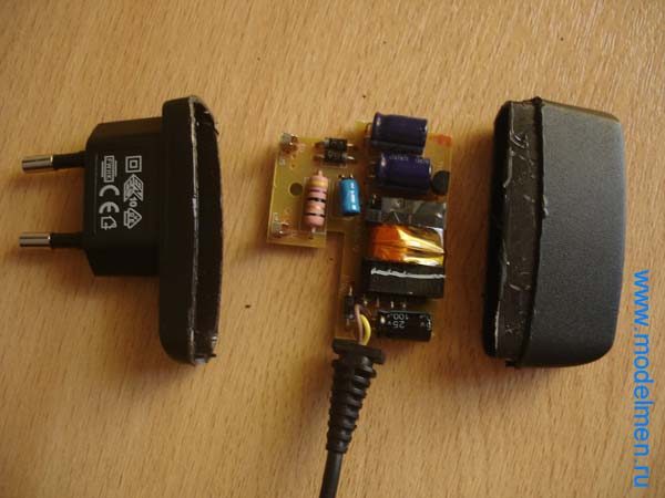
There were several details on the back of the board, the circuit turned out to be not so simple, but still it is not so complicated so as not to fix it yourself.

Below in the photo are the contacts of the inside of the case.

There is no step-down transformer in the charger circuit; an ordinary resistor plays its role. Then, as usual, a couple of rectifying diodes, a pair of capacitors for rectifying the current, then a choke and finally a zener diode with a capacitor complete the chain and output the reduced voltage to a wire with a connector to a mobile phone.

The connector has only two pins.

Now there is no point in assembling a charger for car batteries on your own: there is a huge selection of ready-made devices in stores, the prices for them are reasonable. However, let's not forget that it's nice to do something useful with your own hands, especially since a simple charger for a car battery can be easily assembled from improvised parts, and its price will be penny.
The only thing worth warning about right away: circuits without precise adjustment of the current and voltage at the output, which do not have a cut-off current at the end of the charge, are suitable for charging only lead-acid batteries. For AGM and the use of similar chargers will damage the battery!
How to make the simplest transformer device
The circuit of this charger from a transformer is primitive, but functional and is assembled from available parts - the same way the factory chargers of the simplest type are designed.

At its core, it is a full-wave rectifier, hence the requirements for the transformer: since at the output of such rectifiers, the voltage is equal to the nominal AC voltage multiplied by the root of two, then at 10V on the transformer winding we will get 14.1V at the output of the charger. Any diode bridge is taken with a direct current of more than 5 amperes or assemble it from four separate diodes, with the same current requirements a measuring ammeter is also selected. The main thing is to place it on a radiator, which in the simplest case is an aluminum plate of at least 25 cm2 in area.
The primitiveness of such a device is not only a minus: due to the fact that it has neither regulation nor automatic shutdown, it can be used to "reanimate" sulfated batteries. But do not forget about the lack of protection against polarity reversal in this circuit.
The main problem is where to find a transformer of suitable power (at least 60 W) and with a given voltage. Can be used if a Soviet incandescent transformer comes along. However, its output windings have a voltage of 6.3V, so you will have to connect two in series, rewinding one of them so that in total you get 10V at the output. An inexpensive transformer TP207-3 is suitable, in which the secondary windings are connected as follows:

At the same time, we unwind the winding between terminals 7-8.
Simple charger with electronic regulation
However, you can do without rewinding by supplementing the circuit with an electronic voltage stabilizer at the output. In addition, such a scheme will be more convenient in garage applications, since it will allow you to adjust the charge current when the supply voltage drops, it is also used for small car batteries, if necessary.

The role of the regulator is performed by the composite transistor KT837-KT814, variable resistor regulates the current at the output of the device. When assembling the charging, the 1N754A Zener diode can be replaced with the Soviet D814A.
The variable charger circuit is simple to repeat and easy to surface mount without the need for etching the PCB. However, keep in mind that field-effect transistors are placed on a radiator, the heating of which will be noticeable. It is more convenient to use an old computer cooler by connecting its fan to the charger outputs. Resistor R1 must have a power of at least 5 W, it is easier to wind it from nichrome or fechral yourself or connect 10 one-watt resistors of 10 ohms in parallel. It is possible not to install it, but we must not forget that it protects the transistors in the event of a short circuit.
When choosing a transformer, focus on the output voltage of 12.6-16V, take either an incandescent transformer, connecting two windings in series, or select a ready-made model with the required voltage.
Video: The simplest battery charger
Alteration of the charger from the laptop
However, you can do without looking for a transformer if you have an unnecessary laptop charger at hand - with a simple alteration, we will get a compact and lightweight switching power supply that can charge car batteries. Since we need to get a voltage at the output of 14.1-14.3 V, no ready-made power supply will work, however, the alteration is simple.
Let's take a look at the section of the typical scheme, according to which devices of this kind are assembled:

In them, the maintenance of a stabilized voltage is carried out by a circuit from the TL431 microcircuit, which controls the optocoupler (not shown in the diagram): as soon as the output voltage exceeds the value set by the resistors R13 and R12, the microcircuit lights the optocoupler LED, informs the PWM controller of the converter a signal to reduce the duty cycle of the supplied to the impulse transformer. Hard? In fact, everything is easy to make with your own hands.
Opening the charger, we find not far from the TL431 output connector and two resistors connected to the Ref. It is more convenient to adjust the upper arm of the divider (in the diagram - resistor R13): by decreasing the resistance, we also reduce the voltage at the output of the charger, increasing it - we raise it. If we have a 12 V charger, we need a resistor with a high resistance, if a 19 V charger, then with a lower one.
Video: Charger for car batteries. Short circuit and reverse polarity protection. With your own hands
We solder the resistor and instead of it we install a trimmer, preset by the multimeter to the same resistance. Then, having connected the load (a light bulb from the headlight) to the output of the charger, plug it in and smoothly rotate the trimmer slider, while simultaneously controlling the voltage. As soon as we get a voltage in the range of 14.1-14.3 V, we disconnect the charger from the network, fix the trimming resistor engine with varnish (at least for nails) and assemble the case back. It will take no more time than you spent reading this article.
There are also more complex stabilization schemes, and they can already be found in Chinese blocks. For example, here the TEA1761 microcircuit controls the optocoupler:

However, the principle of adjustment is the same: the resistance of the resistor soldered between the positive output of the power supply and the 6th leg of the microcircuit changes. In the above diagram, two paralleled resistors are used for this (thus, a resistance is obtained that comes out of the standard series). We also need to solder a trimmer instead of them and adjust the output to the desired voltage. Here's an example of one such board:

By dialing, we can understand that we are interested in a single resistor R32 (circled in red) on this board - we need to solder it.
On the Internet, there are often similar recommendations on how to make a homemade charger from computer unit nutrition. But keep in mind that they are all essentially reprints of old articles of the early 2000s, and similar recommendations for more or less modern blocks power supply are not applicable. It is no longer possible to simply raise the voltage of 12 V to the required value in them, since other voltages at the output are also controlled, and they will inevitably "float away" with such a setting, and the protection of the power supply will work. You can use laptop chargers that give out a single output voltage, they are much more convenient for rework.
Today, there are a lot of different wireless chargers. And sometimes it can be difficult to choose the right option from them. Skyway chargers are an excellent solution. They are compact and comfortable. On this moment the company offers two modern devices that will allow you to quickly charge your gadgets.
Skyway Energy Fast
Powerful wireless charger Skyway Energy Fast is designed for fast charging of phones that support QI technology. With it, you can get rid of the wires for charging randomly scattered on the table and the need to constantly recharge your smartphone throughout the day: just put your phone on the Skyway Energy Fast stand and it will automatically start being energized.
Skyway Energy Fast wireless charging will fully charge your phone with Quick Charge in just 2.5 hours. It is 30% faster than a regular wireless charging pad.
With Skyway Energy Fast, you can easily communicate by phone, Skype, WhatsApp, Viber or broadcast to Instagram and Periscope, while your hands will be free, and your smartphone will not run out of power and will even be charged in parallel.
Photo courtesy of SkywayThe presence of two induction coils will make it possible to place the phone on charging not only in a vertical, but also in a horizontal position, in which you can conveniently watch movies on your smartphone without worrying about the fact that it may be discharged.
The ergonomic tilt angle and small size will allow you to comfortably place the charger on the table, while the Skyway Energy Fast QI-charged phone itself will harmoniously fit into any home or office interior.
Skyway Energy Fast significantly reduces the charging time, due to which the phone will heat up less.
Skyway Energy Fast production is under the strict control of Russian Skyway engineers, which ensures high quality assembly and components. Skyway Energy Fast supports models:
Samsung: S9 / S9 + / Note8 / S8 / S8 + / S7 edge / S7 / Note5 / S6 edge plus / S6 edge / S6;
Apple: iPhone 8 / iPhone 8 Plus / iPhone X;
other smartphones that support QI wireless charging.
Skyway flash
The Skyway Flash wireless charger is designed to charge phones that support QI charging technology. With it, you don't have to recharge the device during the day: just put it on the stand, and it will start charging itself.

Such a charging station provides uninterrupted conversations on a smartphone, communication in instant messengers, and broadcasting in social networks. At the same time, the hands will not be occupied, and the phone's charge level will not only not decrease, but even increase.
Such a charger can also be easily placed on the table: both at work and at home. And this will not violate the design of the room at all. The rubber gasket on the bottom will allow you to securely attach your smartphone to the table.
Security Skyway Flash on the highest level: Charging is reliably protected from short circuit, overcharge, overdischarge, overload and overheating of the phone.
Skyway Flash supports the following models:
Samsung S9 / S9 + / Note8 / S8 / S8 + / S7 edge / S7 / Note5 / S6 edge plus / S6 edge / S6;
Apple iPhone 8 / iPhone 8 Plus / iPhone X;
other smartphones that support QI wireless charging.
 How to switch to “Smart mini” tariff from MTS for free - how to connect or disconnect TP?
 Beeline bonuses: accrual, accumulation, use
 How to call America is not difficult