Optical fiber splicing process. Fiber optic network repair, fiber welding
Welding services for FOCL (optical cable, optics, fiber optics) in Moscow and the Moscow region.
In the material and technical base of our kthe company has its own certified equipment for testing and welding fiber-optic communication lines
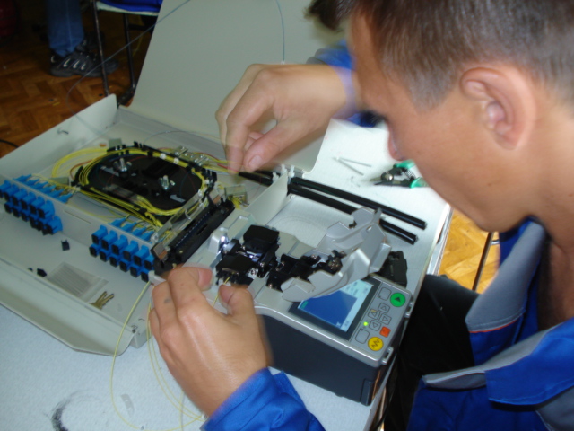
( Optical fiber welding in optical distribution frames
22U rack mount)
OUR FIBER WELDING PRICES
| 1 | Splicing from 32 fibers in a sleeve | 150 |
| 2 | Splicing from 32 fibers in cross | 170 |
| 3 | Splicing 16-31 fibers | 230 |
| 4 | Splicing 8-15 fibers | 230 |
| 5 | Splicing 1-7 fibers | 300 |
| 7 | Optical cable stripping | is free |
| 8 | Working with the coupling (cutting + shrinkage) | 300 |
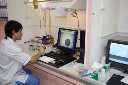
| 9 | OTDR testing (1 fiber) | 100 |
| 10 | Departure in Moscow | 450 |
| 11 | Departure to the region up to 60 km from MKAD | 1 300 |
| 12 | Departure more than 60 km from MKAD | great dane |
The price includes all the work necessary to create an optical line - cutting the optical fiber and laying the spliced fibers into a splice cassette, the cost of the work also includes the departure of a specialist within Moscow and work for splicing up to 16 fibers.
We work with cash and non-cash payments. Call by phone 8-495-532-82-32 from 08 to 20 hours.
The assembly of the optical distribution frame (installation of the optical distribution frame on a wall or in a tripod) is not included in the cost of work. All additional work is carried out by prior arrangement.
For all types of work, we give a guarantee up to 3 years from the date of commissioning of the object, which is directly prescribed in the contract (contract or subcontract).
The material and technical base of the organization includes the following equipment:
- Fujikura FSM-60S welding machine - 5 sets
- Fujikura FSM-17S welding machine - 1 set
- Sumitomo Type-39 welding machine - 1 set
- Reflectometer Exfo FTB-100 - 2 pcs.
- Reflectometer Exfo FTB-200 - 2 pcs.
- Reflectometer Exfo AXS-110-23B - 1 pc.
- FOCL welders-5 brigades,
Measuring group:2 engineers - meters our company has a state-recognized certificate of training at the GOU SPO College of Communications No. 54 under the program "Construction, installation and operation of FOCL", including measurements of FOCL parameters, welding of optical fibers, installation of couplings, terminal crosses, and emergency recovery operations.
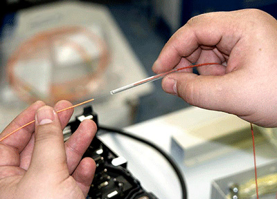
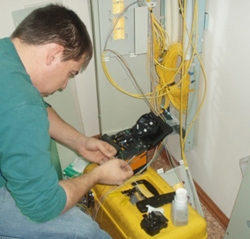
Almost any fiber-optic communication network is a cable assembly divided into certain sections, and each of these sections carries its own load. Periodically, in order to make changes to the structure of the network, it is necessary to separate it, as well as the subsequent welding of optics.
For these purposes, special devices are used for fiber splicing, which are called, for simplicity, welding machines. But unlike conventional devices, the fiber splicing process takes place using fundamentally different welding methods. Optics welding tools even in their own way appearance They bear little resemblance to equipment for arc or any other welding.
Welding optics- this is a very delicate process that requires high professional training from the work performer. This was the case until recently, when easy-to-operate and fairly compact modern welding machines appeared on the market. After that, welding the optics does not require a lot of time and the operator no longer needs to perform any manipulation of the buttons. New generation welding machines are equipped with automatic system, which recognizes the cross-section of the cable, and also have 5-10 programmed welding modes.
(welding of optical fiber in a cross-section using the Fujikura FSM-17S device)
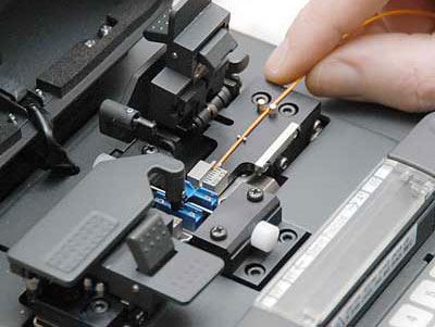
When welding optical fiber
it is enough to place the parts of the cable to be connected into the device, and then close the upper casing. In some individual models of welding machines, immediately after closing the casing, the welding process begins, which takes place completely automatic mode... In other models, you only need to enter the appropriate welding code set, which will serve as a command to start the process.
Many fusion splicers already have a defined program of standard fiber optic fusion work with the most commonly used cable types. Welding of optics can also be carried out in the user (individual) mode, for which there is a reserve of memory space in the standard models. In this case, fiber optic welding allows you to add 20-50 own modes of welding. Although fiber splicing usually does not require such a large number of modes, since in our country no more than 10 brands of fiber optic cable are traditionally used.
And if rare fiber modifications are used in the work, then it is enough just to set the required custom splice mode. In this case, the welding of the optics may take a little longer, since the device will have to go to new settings and deviate from its standard settings.
The advantage of modern optical fiber splicers is their low weight and small size, which is very important for laying a network in a confined space when welding is difficult. In this case, devices weighing only 1-3 kg and a length of 10-20 cm are used, which are enclosed in a small case.
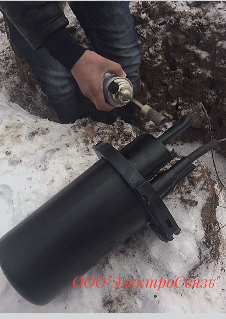
Welding of a fiber-optic cable in a sleeve (laying in the ground)
Used equipment for welding
Sumitomo type 39- another representative of Japanese-made full-automatic welding machines. Sumitomo Type 39 has 2 KDZS ovens, which allows to increase the speed of the complete optical fiber splicing cycle. In the settings of the device, you can activate the automatic start system for both welding and the oven for heat shrinking, so you can completely abandon the use of buttons, which also reduces the time required for the welding process. The device comes with a battery increased capacity allowing up to 200 heat shrink welding cycles. New adjustment system HDCM (High resolution Direct Core Monitoring)
provides higher resolution and image quality of the fibers, which also improves the quality of the spliced joint and increases the accuracy of estimating the loss at the spliced joint. The device also received new, improved fiber holders, which make it easier to work with fibers in the 900 µm buffer.
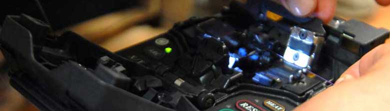
Optical box preparation for fiber splicing
When repairing or building fiber optic lines welding is often used to connect separate sections of an optical cable. Only fiber-optic welding is able to ensure high-quality signal transmission from one cable section to another. The main difficulty lies in the fact that the optical welding process must be carried out using high-tech equipment. This requires a special welding machine, which is not cheap at all. And the qualification of the welder must be at the proper level, because an error during welding can damage the entire optical line.
We list below the main stages in FOCL welding:
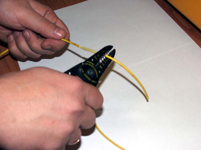
- Preparatory work (cable cutting, optical fiber stripping, installation of couplings);
- Chipping of the ends of optical fibers;
- Installation of fibers in a clamping device on a welding machine;
- Alignment of optical fibers relative to each other;
- Direct splicing of individual fibers;
- Checking the welded assembly;
- Installation of the coupling at the welding site;
- Laying of optical fibers in a splice plate. The specialists of our company carry out work using the automatic welding machine Fujikura FSM-50S. This allows welding work to be carried out with maximum accuracy, and signal loss is minimized.
Our video on FOCL welding.
Fiber optic cable- the most frequently used material used in the creation of data transmission networks. According to the characteristics of the bandwidth, the set of types of transmitted data, reliability and information security it seriously overtakes all types of cable products known today, including copper cable.
So, the maximum possible speed data transmission over fiber optic reaches 10 Gb / sec. It instantly transmits huge volumes of video, voice and data signals over distances of hundreds of kilometers.
 When transferring information fiber optics does not use electricity, but light pulses. Accordingly, electromagnetic interference is not scary to it. Impossible without physically connecting to the line and listening to transmitted signals. In this case, any such intrusion is immediately detected, since it adversely affects the intensity of light emission and, accordingly, the passage of the signal.
However, sooner or later, and fiber optic cables need repair. Among several technologies that restore their work, in the first place in terms of demand and reliability is welding.
 Myself welding process is a connection of fibers (cores) of a cable under the influence of the highest temperature. This is a very demanding job that requires, without exaggeration, jewelry precision.
Complex of welded works consists of several stages:
1. Preparation
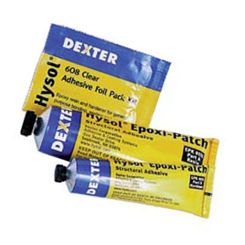
 It consists in the competent removal of insulation (from the optical cable itself and its individual modules), in cleaning the fibers from the hydrophobic gel, and their ends from varnish and a protective layer. Next, a device called KDZS is put on the cores of one of the wires at the junction. This is a special protective kit.
2. Chipping
 This procedure uses a precision cleaver that cleaves the fiber protected by the sleeve perpendicular to the fiber axis or at the desired angle. This is an extremely important stage, the accuracy of which determines the amount of losses introduced into welded joint up to complete spoilage cable... Therefore, it is very important to entrust such work to professionals.
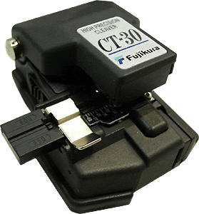 WrightScan engineers have many years of experience in fiber-optic welding. They use only high quality modern equipment. In particular, the Japanese Fujikura CT-30A cleaver with an average cleavage angle ranging from minimum 0.3 before maximum 0.5 degrees. This is an excellent performance compared to inexpensive chipped models. about 2-3 degrees. The smaller the angle, the better the weld quality.
 Performed special welding machines, in the clamps of which are designed for fiber splicing... Priority is given to automatic robotic devices.
The specialists of the company "WrightScan" use for fiber optic welding Sumitomo Type-39 devices. New development the Japanese manufacturer is distinguished by the ability to obtain a sharper image of the fibers. The know-how lies in the application of the revolutionary Fiber Alignment System (HDCM, High Resolution) - the next important step in splicing. Alignment is the alignment of the fibers. This is done by automatic manipulators under a microscope (the device is equipped with a large, color, two-position LCD display with the possibility of 320x magnification). Sumitomo Type-39's special image processing algorithm ensures record-high quality of welded joints, as well as the highest accuracy in estimating losses.
 Further, the robot performs direct welding of the fiber joints due to the electric arc heated to the required temperature. By the way, there are about 48 programs in the aforementioned device. fiber splicing, and for the heating unit - about two dozen more. Nine seconds - and welding completed.
The next steps are a mechanical strength check, an assessment of the attenuation introduced by the joint, and an OTDR trace.
It should be noted that attenuation testing the power of the optical signal is produced not only after fiber optic cable welding... This is one of the most important installation, experimental testing, commissioning and repair operations. Its essence lies in measuring the optical power of the cable, as well as determining the radiation source. However, optical testers are most in demand when performing a complex fiber optic welding, since they are used to measure the amount of attenuation obtained after connecting the fibers of the optical signal power.
To assess the signal power level in the fiber, the specialists of the "RightScan" company use high-quality testers from leading manufacturers. In particular, we are talking about single-mode tester 3M Photodyne and a meter working with multimode cables - Red hawk modifications OM-903/901.

These devices are capable of not only evaluating attenuation rate in accordance with the requirements of the adopted standards, but also to determine the length of the fiber-optic line, the signal delay coefficient, as well as the presence and number of non-detachable splices and connectors.
Singlemode fiber optic cable (labeled 9 to 125) is excellently tested with the 3M Photodyne 17XT. The apparatus consists of a source of optical attenuation and a direct photodetector. The attenuation level recorded by the receiver gives information about how well the product was produced. welding works.
The device is simple, reliable and convenient to use, operates in the range of 780-1550 nanometers, is equipped with a large LCD-display and does not lose the quality of research even at sub-zero temperatures.
Multimode fiber optic cable (grades with parameters 50 or 62.5 to 125) is much more complex in structure. Attenuation rates in such lines are well measured by the aforementioned Red Hawk instrument. It is built in a similar way to 3M Photodyne, but is more powerful.
For all its functionality, unambiguously testers they can only report whether or not the welding was done "in a straight line". This can be understood from the measurement protocols (printed in A4 format) obtained from the results testing... They give a very clear picture of signal attenuation. In addition, optical testers are indispensable when working on old cables (already welded). For example, they can determine the serial number of the fiber without disassembling the optical crosses.
However, count on the fact that optical tester will be able to point out a specific problem in the line, it is not worth it: he will not "see" either an optical fiber break, or poor welding in the sleeve, or a critical bend of the cable itself. All these tasks are the prerogative of a stronger instrument - optical reflectometer... The same device with microscopic accuracy will be able to point to the place of the problem and calculate the distance to it.
Taking a trace also called certification of the network, since this operation gives a comprehensive understanding of all the known parameters of fiber-optic lines. For its implementation, special powerful devices are used - reflectometers, which are available both in the format of individual devices and in the form of set-top boxes.
 In fact, reflectometers are more intelligent, highly sensitive and highly targeted optical testers. Modern reflectometers universal: it does not matter for them which cable to investigate: single-mode or multi-mode. The most powerful representatives of this technique have several measurement modes, including automatic. Also the advantages of modern reflectometers is a large set of advanced functions, with the help of which various test configurations for fiber optic... In addition, these devices have the ability to save measurement results, display the results of tests of fiber-optic lines ( reflectogram), as well as make detailed report details.
 In fact, this is cable passport, which remains with the owner of the network a kind of standard: it is with the fixed parameters that the fresh readings of the line research are compared in the future and competent technical decisions are made.
OTDR operating principles consist in the generation of short pulses of optical radiation, which would pass along the fiber, and the subsequent registration of the return scattering signals.
 The specialists of the company "RightScan" use exclusively high-quality, reliable and faultlessly proven reflectometers... In particular, network certification is performed using an Anritsu MW9076B1 four-wave OTDR device. It is a new, lightweight instrument that accurately measures losses and identifies faults in fiber optic cables.
Anritsu of this modification is distinguished by a serious dynamic range (45 dB). This allows the OTDR to operate at unprecedented long distances - up to 190 km, as well as to have short “dead” zones in attenuation (no more than 8 m). It is the best choice for installation and maintenance fiber optic lines medium range, since it flawlessly detects all types of malfunctions, including local area networks(LAN, SCS).  This model reflectometer works with high resolution reflectograms(5 cm), which makes it possible to calculate up to 50 points on the graph. The device is independently capable of giving a conclusion whether the investigated cable is good or bad, based on the requirements of industry standards (TIA 568c, IEEE 802.3ah, etc.). Anritsu MW9076B1 can also be used for diagnostics of the ends of optical connectors different types.
Taking a trace hard to underestimate: it is a complete fiber optic line diagnostics... It makes sense to conduct such an audit not only after welding on fiber. If the line was laid long enough or not by the most qualified installers (who do not leave any truly valuable information about the work done), it makes sense for the user to make it fresh reflectogram before communication problems occur.
The specialists of the company "WrightScan" examine your fiber optic network quickly and efficiently. The results of comprehensive research will be reflected in a detailed report, both in printed form (in the size of standard office documents) and in electronic form. At the same time, our OTDRs store data in universal format which can be opened in many programs. As a bonus, we can set required applications for viewing and editing OTDR traces on your office PC.
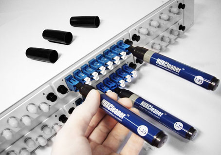
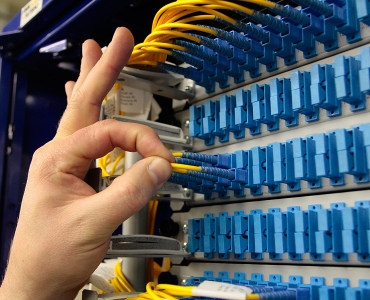
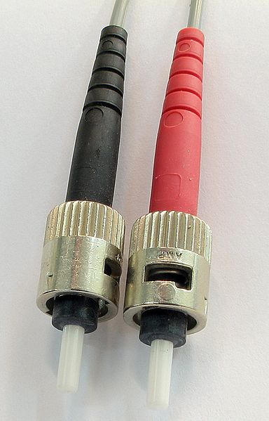 The structure of fiber optic cables cannot be imagined without such an element as connector(Subscriber Connector). This is about fiber optic connector general use, used both in single-mode and multi-mode fibers of networks of various sizes. Thanks to connectors you can not only provide connection to receivers and light sources, but also check fibers, and quickly change the configuration of equipment.
Connecting to a connector carried out by means of fiber optic patchcords. They are designed to establish switching between ports of one or another active line equipment.
The more tightly the ends of the fibers are in contact when they are connected to the connector, the less will be the back reflection of the signal and, accordingly, the higher the quality of communication. Connector polishing is needed precisely for this task: thanks to this operation, the possibility of an air gap between the connecting surfaces of the fibers is eliminated and the reflectivity is reduced.
Polishing types the ends of the fibers differ in the form of processing of the connector (flat, rounded, at an angle) and the degree of application of nano-processing. In some cases, glue polishing technology is also used, which should be discussed in more detail.
Let's start with the fiber inside connector is in the ferrule. This tip is the most valuable thing in an optical connector. Most often it is made of ceramic, has the shape of a cylinder or a cone and a diameter of 1.25 to 2.5 mm.
 Fixed optical fiber in the ferrule either mechanically (clamping using polymeric materials) or chemically (using glue). The second technology is of higher quality and more durable. In particular, it is practiced in factories that make pigtails and patchcords.
In fairness, it should be noted that glue polishing not suitable for all types connectors... It is unambiguously applicable for multimodes 62.5 or 50 to 125. The positive aspects of the technology include guaranteed ensuring the reliability of the line, because there is excluded an unnecessary link of the "cable-pigtail" type. but adhesive technology more expensive, takes longer than welding and, most importantly, it requires a lot of experience and professionalism. Inept polishing leads to regrinding of the end of the ferrule, which gives colossal return losses. Therefore, this operation can only be trusted by highly qualified specialists.
Employees of the company "WrightScan" engaged in polished connectors, have won the trust of many clients in Moscow and the Moscow region. This operation is carried out exclusively by qualified workers with impressive professional experience. Created and reconstructed by them fiber optic lines work for a long time, reliably and smoothly.
 Our specialists work on two adhesive polishing technologies: EPOXY and Hot Melt. The algorithm of work of both begins and ends in the same way: traditional stripping of the cable, as well as chipping and polished fiber, respectively. But the gluing process for these technologies is different. If Hot Melt assumes the presence of ready-made factory glue (it is pre-filled into the connectors), then when using EPOXY, the master needs to prepare a special two-component composition himself and pump it into the connectors. Further in connector the stripped end of the fiber is inserted with glue, a protective cap is put on the ferrule, and all this is sent to a special oven for the polymerization of the substance for about a quarter of an hour. According to Hot Melt - on the contrary - at first it heats up in the oven connector and then the fiber is inserted into it. Polymerization occurs as the adhesive cools.
 The chipping process in both cases is identical: with special tools resembling a fountain pen with a blade at the end, from the ends connectors excess fiber is removed. The flawlessness of subsequent polishing depends on the quality of the chip. By the way, this process is also the same in both technologies: meticulous work on processing the protruding tip fiber optic produced on the finest polishing film three degrees of abrasiveness (from 5 to 1 micron) in decreasing order.
For comparison: with mechanical fiber fixation, the cleavage is carried out simply to the border of the fixator, and the connector is only slightly polished special micro-disks, and even then not always. Accordingly, the reflectivity in such lines is higher, and the quality of the commutation is worse.
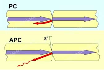
Different experts name three to four types polishing connectors: flat end (PC and SPC); convex (UPC); and beveled end (APC). Losses for single-mode for all of them are standard - about -0.2 decibels, but the level of return loss varies: from -30 to -60 dB, respectively.
Optical fiber splicing- by far the most advanced technology permanent connection fibers.
The fiber splicing process takes about 9 seconds.
Optics splicing is the ideal way to join optical fiber
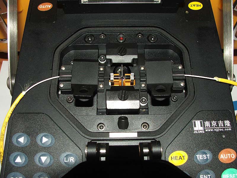
 When installing and laying fiber-optic lines consisting of cable sections of a certain length, welding is used. Optics fusion is the ideal connection method and promotes fast and smooth signal transmission between cables. High-quality welding of optics is achieved by observing all stages and technologies, as well as using high-quality equipment. The brewing of optical fibers is the most critical process on which the operation of the entire line subsequently depends.
All preparatory work must be completed before starting welding.
Clean the ends of the cables by carefully removing the sheathing. For this, a special tool is used that processes fibers with a diameter of up to 900 microns. Then the ends of the cables are degreased with dehydrated alcohol and connected to each other with special cleavers.
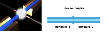
Cleavers perform the specified parameters: angle or length of the chip. With the help of them, high accuracy is achieved at the chipping points. The end of one fiber is placed in a heat-shrink sleeve designed to protect the connection. This is followed directly by the welding process, which can be carried out using manual or automatic devices. The ends of the fibers are placed in these devices, and the display shows their alignment (exact position in relation to each other). Signal propagation through shared cables strongly depends on this accuracy. The fibers are then melted using an electric arc and held together. A special analysis of several indicators (gradient of deformation of the core, refraction of the core) shows how successful the welding was.
A strong connection of the cables to each other is provided by an optical muff coupling. It is a modern construction with a pleasant ergonomic design, easy to install. Recently, the connection of cables with couplings perfectly replaces the wall-mounted optical distribution frame. The installation process of optical couplings is impeded by a mandatory set of test measures aimed at checking the connection with the selected cable. Optical couplings can be branching or connecting. If the sleeves are mounted in the ground when connecting the cable, then it becomes necessary to protect them with steel boxes. Protection of plastic couplings requires the installation of special cabinets. In any case, the couplings must always be accessible for repair and reassembly.
During the construction of a fiber-optic communication line (FOCL), there is a need to connect individual sections of the cable route. The length of an optical cable is tens and hundreds of times less than the length of the trunk, so splicing communication lines is a standard procedure when laying fiber-optic communication lines.
There are two ways to splice a fiber optic cable:
- The mechanical method is by connecting optical fibers using a connector. The method is used infrequently, since its application affects the quality of the signal. This option is suitable for prompt elimination of cable breaks in the field.
- The thermal method (fiber-optic link welding) is a reliable method that provides an integral splicing of cable fibers with each other and a minimum level of signal loss. Carrying out work requires the use of special tools and welding equipment.
Welding of fiber optic cables is the main method of connecting cables when laying and installing fiber-optic communication lines. The availability of equipment, materials and qualified welders as part of the material and technical base is our guarantee that the tasks will be completed on time.
welding equipment
A high level of quality of the optics welded joint and short terms of work are ensured by the use of modern welding machines - equipment with an automatic control system. The splicer splices the fibers of the optical cable and allows on-site testing of the quality of the spliced joint.
Modern welding machines are universal and can weld all types of optical fibers - the mode of welding an optical cable, in accordance with its type, is automatically adjusted.
Optical cable welding
After completing the installation of the cable, its individual construction lengths are welded to each other, the welding place is placed in an optical sleeve. The clutch housing will provide hermetic protection of the optical fiber junction from external factors.
The welding process includes the following operations:
- Preparation of the cable for work: cutting, removing the external insulation and insulation of optical modules, cleaning the fibers with gel. The operations use tools and materials from a special set.
- Joint protection kits (KDZS) are installed on the prepared fibers, which consist of a power rod and heat shrink tubes.
- The ends of the fibers are stripped, after which each fiber is cleaved with an optical cleaver.
- The fibers to be joined are placed in the V-grooves of the welding equipment and aligned (aligned). Alignment accuracy is ensured by performing alignment under a microscope or in automatic mode.
- Welding of an optical cable occurs by heating the ends of the fibers in an electric arc and aligning them. The splice type and parameters are automatically determined according to the machine's assessment of the optical fiber type.
- The equipment automatically evaluates the attenuation and checks the connection for strength.
- KDZS is installed on the welding place, which is placed for heat shrinkage in a heat chamber.
Everything important parameters welding qualities are displayed on the monitor of the welding machine and allow the operator to monitor the conditions of the operations.
An important stage of welding is flaw detection, which is carried out in relation to each weld, immediately after the completion of welding. This operation is included in the list of tasks that can be solved using welding equipment equipped with a laser attachment. The purpose of flaw detection is to determine the degree of signal distortion at the seam, which seriously affects the assessment of the quality of work.
After the completion of the entire complex of welding, the FOCL is diagnosed for the detection and measurement of the main parameters of the fiber-optic cable, the presence of damage and other events. For diagnostics, optical reflectometers (OTDR) are used - devices that determine parameters and states, visualizing data based on the results of diagnostics by building reflectograms.
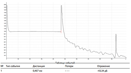
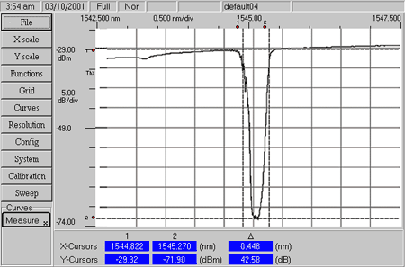
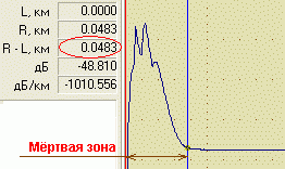
Reflectogram
Trace interpretation and data analysis provide the following data:
- fiber optic cable length;
- location of welded joints and their quality (indicator of welding losses, dB);
- the location of the connectors and their quality (loss and reflection rates, dB);
- the presence and location of damage (breaks, macro bends, cracks);
- other major events, parameters of reflection and losses on them;
- total line losses.
OTDR diagnostics and interpretation of the reflectogram are carried out in the future upon delivery
 Bugs in Singularity?
 Just Cause 2 crashes
 Terraria won't start, what should I do?