The Guide to Software: Useful Overclocking Utilities and More. Undervolting: reduce noise and heat for Kepler video card bios tweaker for mobile cards
This material is intended to guide readers in today's variety of software for tuning, evaluating the performance and overclocking of system components, as well as tracking monitoring data. This article is based on useful links to download the appropriate applications.
Drivers: platform
The correct choice of drivers for various nodes of the system, in particular elements motherboard and the GPU of the video card, is extremely important for the stable operation of the PC. Where special "creativity" is not required, it is when installing the drivers that come with motherboard... Nevertheless, you can always find and install the latest drivers for the chipset, audio controller and wifi cards(if available).
Benchmarking
There are a great variety of methods for evaluating the performance of system nodes, and each experienced enthusiast has his own. Listed below are the most simple ways, and you can conduct in-depth testing using a set of applications from among those mentioned in reviews of processors, video cards, memory modules and other components on our website.
It is a rendering of a 3D scene and is very popular. It is free, shows stable results and can load up to 256 processor threads (256 AMD cores Bulldozer or 128 cores Intel Core with Hyper-Threading). More or less relevant, especially in the context of competitive benchmarking, previous version of this app -
The auxiliary utilities RivaTuner Statistics Server (RTSS) and Fraps will help you measure the frame rate in games that do not have a built-in benchmark. With their help, you can record game videos. Fraps' interface is simpler, but updates to this utility have not been released in almost two years.


So, above we have considered the most useful and demanded programs for enthusiasts for configuring, monitoring, overclocking and testing PC nodes. To date, the choice of utilities for these purposes is huge, and the article, most likely, does not mention all of the applications that you personally use. Write about your own preferences in the comments to this material.
Warming is just around the corner, which means that soon the computer cooling systems will cope worse with their tasks. How to reduce the temperature, noise and power consumption of video cards without spending a single penny on it? Read this article about graphics adapter undervolting.
Undervolting (undervolting) - a term denoting a decrease in voltage and therefore the current used by the video card, which entails a significant decrease in temperature under load (in some cases by 10 degrees). However, this is not the only advantage of undervolting, it also helps to combat the noise of the video card in games.
As a rule, lowering the temperature by even a few degrees allows the fan speed of the active cooler to be reduced, which gives a noticeable difference in noise level. In some programs (MSI Afterburner, Trixx), you can go even further and further reduce the CO noise by adjusting the cooler's algorithm. As a first approximation, you can focus on a temperature of 80 degrees Celsius. That is, change the rotation speed of the fans so that the chip does not warm up above 80 degrees under load. However, this is already another topic, but today we will talk about undervolting.
It is desirable to lower the voltage gradually. For example, from 1.200 V first to 1.150 V, and then in 0.01 steps, that is, to 1.140, 1.130, etc. After each reduction, you can test the stability of the video card, that is, keep it under load for a while. For this, you can use the same FurMark.
Undervolting partly resembles overclocking, only in the opposite direction - instead of increasing the frequency, it is necessary to lower the voltage. After the first failure (the driver will show a message), you should go back one step by increasing the GPU voltage and conduct a thorough stability test in this mode.
Let's consider several ways of undervolting. The first two come down to using special utilities, and the third, more advanced one, for flashing the BIOS of the video card.
Programming method
In the main window of this program there is an adjustable parameter Core Voltage, which is responsible for the voltage level supplied to the video card core. As a rule, this parameter is in the range of 1,100-1,200 V and is set by the manufacturer with some margin.

You can reduce the Core Voltage indicator in principle with any step (but better with a small one), this operation cannot somehow harm the video card. The worst thing that will happen is the computer will freeze, or, more likely, a message will appear in the system tray stating that an error has occurred in the video card driver.
The disadvantage of MSI Afterburner is that it does not allow you to adjust the voltage of not all video cards.
Despite the fact that the name of the Sapphire Trixx application, as in the case of MSI Afterburner, contains a mention of a specific video card manufacturer, the utility works with adapters from all companies, not just those mentioned.

The advantage of Trixx is that this program is able to regulate the voltage of more video cards. In other words, if Afterburner has Core Voltage locked, try Trixx.
The voltage regulation procedure in Trixx is not fundamentally different from that for Afterburner. The required slider is located in the Overclocking tab and is called VDDC.
The only drawback of Trixx in terms of undervolting is that the utility cannot restore the voltage value when the computer is restarted. Only the core and memory frequencies are restored, and the voltage must be set manually each time. Afterburner does not have this disadvantage, but, as mentioned, it supports fewer video cards.
Changing parameters in the video card BIOS
Let's start with the usual warning in such cases. All operations described below you carry out at your own peril and risk. Do not flash the BIOS if you are not sure of the correctness of your actions. Damage or unsuccessful firmware update can damage the video card, voiding the manufacturer's warranty.
So, what if the video card is not supported by Afterburner, and you don’t want to set the voltage manually using Trixx after every PC restart? In this case, you can edit the parameters specified in the BIOS of the video card.
AMD Radeon
To save the BIOS to a file on your computer, you can use the utility GPU-Z or ATIWinflash... The second program is preferable because it will come in handy again later for BIOS updates while GPU-Z will no longer be used.
After saving the BIOS to a file, you need to open it in Radeon BIOS Editor, and on the Clock Settings tab in the Voltage fields set the voltage value selected earlier in Afterburner or Trixx. After that, save the edited BIOS (Save BIOS), preferably in new file.

At the last step, it remains to launch ATIWinflash, select the required video card, if there are several of them in the computer, load the edited BIOS into the program (Load Image) and press the Program button to flash it. The program will "think" for a while, after which it will offer to restart the computer and load the video card with a new voltage value.
NVIDIA GeForce
For NVIDIA graphics cards you will need GPU-Z programs (to save the video card BIOS to a file) and NiBiTor(NVIDIA BIOS Editor) to change the voltage of the video card (Voltages tab, 3D parameter). Note that in some cases a limited voltage range with a certain discreteness or even several specific values will be available for the 3D mode. If the list does not contain what is required, you may have to abandon the idea. BIOS flashing or use a value that is slightly higher than the minimum sufficient.

For video cards based on chips with Kepler and Maxwell architecture (GeForce GTX 6xx / 7xx), you will need the Kepler BIOS Tweaker application. However, given the multiple operating states of GPUs due to the GPU Boost technology, these models often only use a software voltmod.
After editing, the BIOS must be saved to a new file and uploaded to the video card. To do this, download the utility NVFlash, after which the file with the edited BIOS must be flashed. To do this, you need to remember the basics of working with the command line by typing in the console: nvflash.exe -6 BIOS.ROM. In this case, BIOS.ROM is the name of the file with the edited firmware, which should be located in the same directory as the NVFlash.
Outcomes
To ensure stable operation of video cards, manufacturers set the GPU voltage with a certain margin. Often it can be somewhat reduced without obvious consequences for the device itself, thereby reducing GPU heating, and, accordingly, the noise level of the cooling system.
An accompanying bonus of reducing the supply voltage is also a decrease in the power consumption of the video card. In this case, the bill goes to tens of watts for modern high-performance video cards. Whether the game is worth the candle is up to you.
Graphics cards of the Maxwell generation end their era, giving up the power to rule the improved Pascal architecture. But this did not stop the GM20x being interesting in terms of its hidden potential, expressed in MHz. We remember that the introduction of Boost 2.0 technology put a stick in the wheel when overclocking video cards using utilities (MSI Afterburner, EVGA Precision, Palit ThunderMaster and others), and the frequency offset led to the fact that the base and intermediate frequencies changed along with the BOOST frequency, and sooner or later this led to instability when changing the load on the video card. As a result, many reduced overclocking, and for further overclocking they either had to use a microcode editing method called "disabling BOOST" (in fact, the Boost 2.0 technology itself did not disappear anywhere, the video card simply worked at increased frequencies even under light loads), or use third party programs to fix the maximum frequencies (for example -Nvidia PowerMizer Manager). The disadvantages are increased frequencies and voltage in idle mode and light load, as a result - unnecessary heating and consumption. In this case, the capabilities of Maxwell II BIOS Tweaker and the driver part of video cards act as limiters. But what if we look into the thin world of microcode using a HEX editor and see what this approach will give us.
Preparing to edit the microcode of the video card
First, you need to flash the latest BIOS version (no modifications) for your video card. You can find it both on the manufacturer's website and on third-party sites, for example -TechPowerUp. In order to flash the BIOS, you can use the NVFlash program. I recommend immediately downloading the version with bypassing certificate verification, since it is she who will be useful to us further. For the firmware, create a folder in the root of the C drive with the name nvflash and unpack the contents of the previously downloaded archive into it. also add the microcode file to the root of the folder, which we are going to "burn". Then run command line as administrator and enter the following commands in turn:
- cd c: \ nvflash
- nvflash-6 namebios.rom
wherenamebios is the name of the BIOS file.
I mainly use MSI Afterburner for overclocking, so in this material it is she who will appear. Download the latest version and install it. We also download the GPU-Z program and install it.
The next step is to determine the value of the maximum frequency and operating voltage at full load on the video card without using overclocking. It is more convenient to do this using the built-in GPU-Z rendering and sensor monitoring.
On this example the frequency in Boost 2.0 mode is 1455.5 MHz at a voltage of 1.199 V, the second video card (the BIOS of which will be discussed below) worked at a frequency of 1367 MHz at 1.193 V. Let's remember these parameters, they will come in handy for us.
Now open the BIOS version that we loaded into our video card using the Maxwell II BIOS Tweaker. In parallel, we will consider the main tabs and the values presented in them.
Common Tab
.jpg)
TDP Base Entry / 3D Base Entry / Boost Entry - we do not touch these parameters, we leave them as they are.
TDP Base Clock / 3D Base Clock / Boost Clock - the value of the base and BOOST frequencies. In fact, TDP Base Clock / 3D Base Clock does not depend on the asic video card, and we can set it manually, but select frequencies from the Boost table tab. In my example, you see the frequency from 34 table cells.
.jpg)
But the Boost Clock frequency tells us the minimum BOOST frequency for a video card (1329 MHz - 59 cell of the table), but the actual frequency will be determined by the asic card (you can see it in gpu-z) - the higher the asic, the higher the actual frequency in BOOST mode (on my video card with asic 73.5% boost out of the box to 1392.5 MHz - 64 position of the frequency table). By changing the Boost Clock to the values from the table above the stock, we are shifting the BOOST frequency. Changing the frequency from 1329 MHz (59 position of the table) to 1354.5 MHz (61 positions) in my case will lead to a change in the actual frequency in BOOST mode from 1392 MHz (64 cells) to 1418 MHz (66 cells). This will allow changing the maximum boost frequency without using AB. This is a method for the lazy. Also, the Gpu Clock Offset + 13MHz button will do the same, but also change the TDP Base Clock / 3D Base Clock (but you can manually return them to the desired ones).
Temp Target / Max Temp Target - temperature limits, the same sliders are in MSI Afterburner. We set the value to 89/91, provided that the video card does not heat up at 80+ degrees.
Fan Control - control of the speed of the fans of the video card cooling system.
RPM1x / TMP1x / PER1x are the desired RPM limits (when using PWM fans) / temperature / RPM (when using voltage controlled fans) to adjust the valves. It is advisable to adjust the percentages by the calculation method (2600/3200 = 81%, not 70, like mine, but I have PWM control).
How it works.
RPM13 / TMP13 / PER13 - maximum rpm values, leave RPM13 / PER13 unchanged, and set TMP13 to the value that you consider necessary (in my example, 3200 rpm (maximum passport value) at 90 degrees).
RPM11 / TMP11 / PER11 - to these values the gates will be unrolled from zero or the initial values. In the picture above 35 C o, the fans spin from the technically minimum possible value to 1000 rpm, after 35 and up to 70 C o (TMP12) they spin smoothly up to 2600 rpm (RPM12).
To stop the valves RPM11 / TMP11 / PER11 write as 0/0 / XX, where XX is the temperature to which the valves will stand.
Memory Clock - video memory frequency. We put a stable value in your opinion and subtract 100 MHz. For more stability and confidence.
Voltage Table Tab
.jpg)
This tab displays the voltage for each frequency from the frequency table.
If you have a GM200 and this tab looks like this:
.jpg)
then you need to open the second and third lines in the voltage table. To do this, open the BIOS in Kepler BIOS Tweaker and move the selected sliders to an arbitrary position:
.jpg)
It turns out something like this:
.jpg)
The BIOS now looks like this in the Maxwell II BIOS Tweaker:
.jpg)
1 line: the maximum possible voltage (depends on the voltage regulator of your video card, the maximum can be both 1281 and 1250, how lucky you are). We put 1281.3.
2nd line: this is our base voltage for the Boost Clock.
If you want to reduce the stress one step- change the maximum voltage in this line one step down with the keyboard arrows and flash the BIOS with this voltage and perform manipulations with the render in GPU-Z. The resulting voltage (this will be minus the step from your drain voltage) is written with the first value in the second and third lines.
If you don't want to take one step down the stress- set the voltage found during the preparation stage using the GPU-Z render to the minimum and plus one step to the maximum. With this setting, the frequency will NOT reset under the temperature. We set the maximum voltage in this line one step more from the minimum.
3 line: The minimum value is the same as in the second line, the maximum is as in the first. This is exactly the voltage that we can adjust using the sliders through MSI Afterburner.
Software monitoring (GPU-Z, MSI Afterburner, HWiNFO) is not always true and the displayed GPU voltage may be higher / lower than actual. You can verify this with a multimeter.
And now that the displayed voltage steps in the same gpu-z are not the only possible ones. Let's make the change using the example of my video card, the VID of which on the stock BIOS is 1.150, 1.175, 1.193, 1.218, etc.
First, we fix the voltage at 1.175 V to determine the cell number for this voltage. To do this, we put the following values in the first three lines of the stress table:
- 1.281-1.281
- 1.175-1.181
- 1.175-1.281
As a result, we get the BOOST frequency, the corresponding Cell 59.
Next, go to cell 59 in the stress table and shift the values in such a way as to shift the voltage range by the value we need. Having made a table, as in the screenshot, I got a VID card that was not there before. It becomes one of the range for each cell, and, as seen in the video below, the voltage step can be adjusted more precisely.
.jpg)
It is worth considering that for a voltage offset of 6-10 mV, we go to the next cell of the boost table and get +13 MHz. You can change the voltage step, make it more or less.
.jpg)
Power Table Tab
.jpg)
These are the power limits. We are interested in the first 6 groups (each group consists of Min | Def | Max values).
The first group is TDP cards. In fact, this calculated value of heat, which the manufacturer takes into account when designing a cooling system, has nothing to do with the power limit. We set it the same as the values of the 6th group.
The second group - skip it.
Third group - power PCI-E slot, we set this group taking into account 75 W maximum.
.jpg)
The fourth group - the allowed power of the first connector additional food... We put 75,000 for 6-pin and 150,000 for 8-pinPCI-E.
The fifth group is the permitted power of the second auxiliary power connector. We put 75,000 for 6-pin and 150,000 for 8-pinPCI-E.
The sixth group is the power limit. This is what interests us the most. The values are calculated from the sum of the values of all the power supplies of the video card, which we set in the table. We write the same values into 1 group (optional).
Boost Table Tab
.jpg)
Here we see the very table of frequencies, because of which we are gathered here. Each frequency here is coupled with a voltage from the corresponding table, the binding goes according to the cell number. With the help of the Max Table Clock slider, we can shift the frequencies from 35 to 74 cells both upward and downward. This is the same as in MSI Afterburner. Also here we can clearly see that with an increase in the maximum BOOST frequency, all intermediate frequencies also change.
Boost States Tab
We only change the Max GPC in P00 and P02 to the value from 74 cells of the frequency table, the rest does not concern us.
Clock States Tab
In the DDR profile P00 we set the memory frequency from the first tab (more precisely, it will change here when the frequency changes there), but DDR in P02 is either left as it is, or changed to the value as in P00. If we leave it as it is, when using CUDA, it will drop the frequency to this value.
Editing the frequency table using the HEX editor
To begin with, we set the boost voltage we need in the second and third lines in this way (in this example, I lowered the voltage for BOOST to 1.175 V, but it is worth remembering that at the beginning of the article with the help of GPU-Z we have already determined the operating voltage and frequency, so set the voltage you need).
.jpg)
In the second line, we add one step to the right value, in the third we set the maximum value to which the voltage can be raised through MSI Afterburner. It should be borne in mind that when the voltage increases with the help of MSI Afterburner, the voltage during heating will decrease to the minimum specified in the second line.
We remember in which cell the 3D Base Clock frequency is located:
.jpg)
On the BOOST position (on my copy of the video card at 1.174 V this is 59 cells,) set the frequency, which is stable at this voltage (I recommend setting it 2-3 steps lower, adjust the rest in MSI Afterburner).
.jpg)
Next, open the BIOS in any HEX editor (I used HxD) and look for the BOOST cell as follows: add 12 to the cell number (in my example, 59 + 12 = 71) and convert it to hex (71d = 47h). Next, we take the frequency on this cell (1455.5 for me), multiply by 2 (1455.5 * 2 = 2911) and convert it to hex (2911d = 0B5Fh). We do not lose zero. Next, we look for the following hexadecimal sequence in the HEX BIOS code: 47 5F 0B 00 01
.jpg)
Where 47 - hex-code of cell BOOST, 5F 0B- doubled frequency with the least significant digits forward (0B_5F), 00 01 - command code. To the left (from the 46th position) there are cells from 58 to 1 groups of 5. We take the frequency value that we will have between the base frequency and the BOOST frequency (I chose 1405 MHz), translate it into a familiar format (1405 * 2 = 2810d = 0AFAh) and we insert them from the cell before the boost (58 in my case) to the one on which the base frequency + 1 (43 + 1 = 44) stood and change them to the value we need (FA 0A). After editing the frequency table, we correlate the values in the voltage table (one voltage range can be set for all cells with the same frequency), save the BIOS (be sure to then open it in Maxwell II BIOS Tweaker and save it to rewrite the checksum) and flash it.
.jpg)
.jpg)
You can write any frequencies, choose any step, but the tweaker can cross out frequencies that are not crammed into it. It's okay, this is a flaw in the program, Kepler BIOS Tweaker also shows BIOS from Maxwell.
.jpg)
.jpg)
Conclusion
Overclocking video cards has several reasons. This is sporting interest, and the need for a few extra frames per second, or just the pursuit of beautiful numbers. In this article, we looked at a small example of how to get rid of the sticks inserted into our wheels during acceleration. Boost 2.0 technology, in my opinion, is no different from the program sequence of cause and effect, so changing conditions leads to a change in the operating mode. Using the HEX editor and changing the voltage and frequency tables, I achieved unprecedented results on the GTX 980 TI (using air cooling) - with a core frequency of 1592 MHz and an effective video memory frequency of 8500 MHz at a voltage of 1.27 V software application Firestrike from the 3DMark package achieved 22666 graphics points, in Firestrike Extreme at the same voltage and 1596/8400 MHz, respectively, the result was 10641 graphics points.
For games, the use of this technique also turned out to be quite useful. For example, absolute stability at a core frequency of 1558 MHz (memory frequency was 8400 MHz) under any load was achieved at 1.199 V.
By lowering the operating voltage, the video card turned out to be cold and almost silent. At a voltage of 1.143 V, the video card worked at a frequency of 1503 MHz.
In this case, the frequency was set with a certain margin
.jpg)
When the load was changed, there were no many intermediate frequencies, there was a BOOST frequency, the base and the only intermediate one, for which a stable voltage was selected for it. At the same time, the energy saving functions worked correctly, as you can see in the picture above.
Be creative, adjust the BIOS for yourself and your needs, but remember that you do all the manipulations at your own peril and risk. Happy and stable overclocking!
Graphics cards of the Maxwell generation end their era, giving up the power to rule the improved Pascal architecture. But this did not stop the GM20x being interesting in terms of its hidden potential, expressed in MHz. We remember that the introduction of Boost 2.0 technology put a stick in the wheel when overclocking video cards using utilities (MSI Afterburner, EVGA Precision, Palit ThunderMaster and others), and the frequency offset led to the fact that the base and intermediate frequencies changed along with the BOOST frequency, and sooner or later this led to instability when changing the load on the video card. As a result, many people reduced overclocking, and for further overclocking they either had to use a microcode editing method called "disabling BOOST" (in fact, the Boost 2.0 technology itself did not disappear anywhere, the video card simply worked at higher frequencies even under light loads), or use third-party programs for fixing the maximum frequencies (for example -Nvidia PowerMizer Manager). The disadvantages are increased frequencies and voltage in idle mode and light load, as a result - unnecessary heating and consumption. In this case, the capabilities of Maxwell II BIOS Tweaker and the driver part of video cards act as limiters. But what if we look into the thin world of microcode using a HEX editor and see what this approach will give us.
Preparing to edit the microcode of the video card
First, you need to flash the latest BIOS version (no modifications) for your video card. You can find it both on the manufacturer's website and on third-party sites, for example -TechPowerUp. In order to flash the BIOS, you can use the NVFlash program. I recommend immediately downloading the version with bypassing certificate verification, since it is she who will be useful to us further. For the firmware, create a folder in the root of the C drive with the name nvflash and unpack the contents of the previously downloaded archive into it. also add the microcode file to the root of the folder, which we are going to "burn". Then run the command line as administrator and enter the following commands in turn:
- cd c: \ nvflash
- nvflash-6 namebios.rom
wherenamebios is the name of the BIOS file.
I mainly use MSI Afterburner for overclocking, so it will be featured in this article. Download the latest version and install it. We also download the GPU-Z program and install it.
The next step is to determine the value of the maximum frequency and operating voltage at full load on the video card without using overclocking. It is more convenient to do this using the built-in GPU-Z rendering and sensor monitoring.
In this example, the frequency in Boost 2.0 mode is 1455.5 MHz at a voltage of 1.199 V, the second video card (the BIOS of which will be discussed below) worked at a frequency of 1367 MHz at 1.193 V. Let's remember these parameters, they will still be useful to us.
Now open the BIOS version that we loaded into our video card using the Maxwell II BIOS Tweaker. In parallel, we will consider the main tabs and the values presented in them.
Common Tab
TDP Base Entry / 3D Base Entry / Boost Entry - we do not touch these parameters, we leave them as they are.
TDP Base Clock / 3D Base Clock / Boost Clock - the value of the base and BOOST frequencies. In fact, TDP Base Clock / 3D Base Clock does not depend on the asic video card, and we can set it manually, but select frequencies from the Boost table tab. In my example, you see the frequency from 34 table cells.
But the Boost Clock frequency tells us the minimum BOOST frequency for a video card (1329 MHz - 59 cell of the table), but the actual frequency will be determined by the asic card (you can see it in gpu-z) - the higher the asic, the higher the actual frequency in BOOST mode (on my video card with asic 73.5% boost out of the box to 1392.5 MHz - 64 position of the frequency table). By changing the Boost Clock to the values from the table above the stock, we are shifting the BOOST frequency. Changing the frequency from 1329 MHz (59 position of the table) to 1354.5 MHz (61 positions) in my case will lead to a change in the actual frequency in BOOST mode from 1392 MHz (64 cells) to 1418 MHz (66 cells). This will allow changing the maximum boost frequency without using AB. This is a method for the lazy. Also, the Gpu Clock Offset + 13MHz button will do the same, but also change the TDP Base Clock / 3D Base Clock (but you can manually return them to the desired ones).
Temp Target / Max Temp Target - temperature limits, the same sliders are in MSI Afterburner. We set the value to 89/91, provided that the video card does not heat up at 80+ degrees.
Fan Control - control of the speed of the fans of the video card cooling system.
RPM1x / TMP1x / PER1x are the desired RPM limits (when using PWM fans) / temperature / RPM (when using voltage controlled fans) to adjust the valves. It is advisable to adjust the percentages by the calculation method (2600/3200 = 81%, not 70, like mine, but I have PWM control).
How it works.
RPM13 / TMP13 / PER13 - maximum rpm values, leave RPM13 / PER13 unchanged, and set TMP13 to the value that you consider necessary (in my example, 3200 rpm (maximum passport value) at 90 degrees).
RPM11 / TMP11 / PER11 - to these values the gates will be unrolled from zero or the initial values. In the picture above 35 C o, the fans spin from the technically minimum possible value to 1000 rpm, after 35 and up to 70 C o (TMP12) they spin smoothly up to 2600 rpm (RPM12).
To stop the valves RPM11 / TMP11 / PER11 write as 0/0 / XX, where XX is the temperature to which the valves will stand.
Memory Clock - video memory frequency. We put a stable value in your opinion and subtract 100 MHz. For more stability and confidence.
Voltage Table Tab
This tab displays the voltage for each frequency from the frequency table.
If you have a GM200 and this tab looks like this:
then you need to open the second and third lines in the voltage table. To do this, open the BIOS in Kepler BIOS Tweaker and move the selected sliders to an arbitrary position:
It turns out something like this:
The BIOS now looks like this in the Maxwell II BIOS Tweaker:
1 line: the maximum possible voltage (depends on the voltage regulator of your video card, the maximum can be both 1281 and 1250, how lucky you are). We put 1281.3.
2nd line: this is our base voltage for the Boost Clock.
If you want to reduce the stress one step- change the maximum voltage in this line one step down with the keyboard arrows and flash the BIOS with this voltage and perform manipulations with the render in GPU-Z. The resulting voltage (this will be minus the step from your drain voltage) is written with the first value in the second and third lines.
If you don't want to take one step down the stress- set the voltage found during the preparation stage using the GPU-Z render to the minimum and plus one step to the maximum. With this setting, the frequency will NOT reset under the temperature. We set the maximum voltage in this line one step more from the minimum.
3 line: The minimum value is the same as in the second line, the maximum is as in the first. This is exactly the voltage that we can adjust using the sliders through MSI Afterburner.
Software monitoring (GPU-Z, MSI Afterburner, HWiNFO) is not always true and the displayed GPU voltage may be higher / lower than actual. You can verify this with a multimeter.
And now that the displayed voltage steps in the same gpu-z are not the only possible ones. Let's make the change using the example of my video card, the VID of which on the stock BIOS is 1.150, 1.175, 1.193, 1.218, etc.
First, we fix the voltage at 1.175 V to determine the cell number for this voltage. To do this, we put the following values in the first three lines of the stress table:
- 1.281-1.281
- 1.175-1.181
- 1.175-1.281
As a result, we get the BOOST frequency, the corresponding Cell 59.
Next, go to cell 59 in the stress table and shift the values in such a way as to shift the voltage range by the value we need. Having made a table, as in the screenshot, I got a VID card that was not there before. It becomes one of the range for each cell, and, as seen in the video below, the voltage step can be adjusted more precisely.
It is worth considering that for a voltage offset of 6-10 mV, we go to the next cell of the boost table and get +13 MHz. You can change the voltage step, make it more or less.
Power Table Tab
These are the power limits. We are interested in the first 6 groups (each group consists of Min | Def | Max values).
The first group is TDP cards. In fact, this calculated value of heat, which the manufacturer takes into account when designing a cooling system, has nothing to do with the power limit. We set it the same as the values of the 6th group.
The second group - skip it.
The third group is the power of the PCI-E slot, we set this group taking into account 75 W maximum.
The fourth group is the permitted power of the first auxiliary power connector. We put 75,000 for 6-pin and 150,000 for 8-pinPCI-E.
The fifth group is the permitted power of the second auxiliary power connector. We put 75,000 for 6-pin and 150,000 for 8-pinPCI-E.
The sixth group is the power limit. This is what interests us the most. The values are calculated from the sum of the values of all the power supplies of the video card, which we set in the table. We write the same values into 1 group (optional).
Boost Table Tab
Here we see the very table of frequencies, because of which we are gathered here. Each frequency here is coupled with a voltage from the corresponding table, the binding goes according to the cell number. With the help of the Max Table Clock slider, we can shift the frequencies from 35 to 74 cells both upward and downward. This is the same as in MSI Afterburner. Also here we can clearly see that with an increase in the maximum BOOST frequency, all intermediate frequencies also change.
Boost States Tab
We only change the Max GPC in P00 and P02 to the value from 74 cells of the frequency table, the rest does not concern us.
Clock States Tab
In the DDR profile P00 we set the memory frequency from the first tab (more precisely, it will change here when the frequency changes there), but DDR in P02 is either left as it is, or changed to the value as in P00. If we leave it as it is, when using CUDA, it will drop the frequency to this value.
Editing the frequency table using the HEX editor
To begin with, we set the boost voltage we need in the second and third lines in this way (in this example, I lowered the voltage for BOOST to 1.175 V, but it is worth remembering that at the beginning of the article with the help of GPU-Z we have already determined the operating voltage and frequency, so set the voltage you need).
In the second line, we add one step to the right value, in the third we set the maximum value to which the voltage can be raised through MSI Afterburner. It should be borne in mind that when the voltage increases with the help of MSI Afterburner, the voltage during heating will decrease to the minimum specified in the second line.
We remember in which cell the 3D Base Clock frequency is located:
On the BOOST position (on my copy of the video card at 1.174 V this is 59 cells,) set the frequency, which is stable at this voltage (I recommend setting it 2-3 steps lower, adjust the rest in MSI Afterburner).
Next, open the BIOS in any HEX editor (I used HxD) and look for the BOOST cell as follows: add 12 to the cell number (in my example, 59 + 12 = 71) and convert it to hex (71d = 47h). Next, we take the frequency on this cell (1455.5 for me), multiply by 2 (1455.5 * 2 = 2911) and convert it to hex (2911d = 0B5Fh). We do not lose zero. Next, we look for the following hexadecimal sequence in the HEX BIOS code: 47 5F 0B 00 01
Where 47 - hex-code of cell BOOST, 5F 0B- doubled frequency with the least significant digits forward (0B_5F), 00 01 - command code. To the left (from the 46th position) there are cells from 58 to 1 groups of 5. We take the frequency value that we will have between the base frequency and the BOOST frequency (I chose 1405 MHz), translate it into a familiar format (1405 * 2 = 2810d = 0AFAh) and we insert them from the cell before the boost (58 in my case) to the one on which the base frequency + 1 (43 + 1 = 44) stood and change them to the value we need (FA 0A). After editing the frequency table, we correlate the values in the voltage table (one voltage range can be set for all cells with the same frequency), save the BIOS (be sure to then open it in Maxwell II BIOS Tweaker and save it to rewrite the checksum) and flash it.
You can write any frequencies, choose any step, but the tweaker can cross out frequencies that are not crammed into it. It's okay, this is a flaw in the program, Kepler BIOS Tweaker also shows BIOS from Maxwell.
Conclusion
Overclocking video cards has several reasons. This is sporting interest, and the need for a few extra frames per second, or just the pursuit of beautiful numbers. In this article, we looked at a small example of how to get rid of the sticks inserted into our wheels during acceleration. Boost 2.0 technology, in my opinion, is no different from the program sequence of cause and effect, so changing conditions leads to a change in the operating mode. Using a HEX editor and changing the voltage and frequency tables, I achieved unprecedented results on the GTX 980 TI (using air cooling) - with a core frequency of 1592 MHz and an effective video memory frequency of 8500 MHz at a voltage of 1.27 V in the Firestrike software application from the package 3DMark achieved a result of 22666 graphic points, in Firestrike Extreme at the same voltage and 1596/8400 MHz, respectively, the result was 10641 graphic points.
For games, the use of this technique also turned out to be quite useful. For example, absolute stability at a core frequency of 1558 MHz (memory frequency was 8400 MHz) under any load was achieved at 1.199 V.
By lowering the operating voltage, the video card turned out to be cold and almost silent. At a voltage of 1.143 V, the video card worked at a frequency of 1503 MHz.
In this case, the frequency was set with a certain margin
When the load was changed, there were no many intermediate frequencies, there was a BOOST frequency, the base and the only intermediate one, for which a stable voltage was selected for it. At the same time, the energy saving functions worked correctly, as you can see in the picture above.
Be creative, adjust the BIOS for yourself and your needs, but remember that you do all the manipulations at your own peril and risk. Happy and stable overclocking!
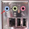 How do I enable line-in?
 Recovering deleted files from a USB flash drive
 Installing windows 8 64 bit