LED backlight for LCD TV. Repair LED TV backlight at home. What does the price depend on
If, after turning on the LCD TV panel, the user hears sound, but there is no image on the screen, this may indicate a failure of the LED backlight. To diagnose and troubleshoot, you can call a representative of the service center, but, knowing the procedure, having spare parts and the necessary tools, you can repair the TV's LED backlight with your own hands. The rules and algorithm of actions of this process are later in the material.
Causes and symptoms of faulty backlight
The TV screen consists of many dots - pixels located close to each other, and in order for the user to see the image, light must be supplied to them, then they “come to life” and form a picture. LED technology in LCD TVs is a new way of backlighting the screen using LEDs, which has replaced CCFL fluorescent lamps. LED-backlit devices are characterized by excellent color reproduction, high contrast, incredible clarity and realism of the image, low power consumption and small thickness.
Backlight types
Depending on how the LEDs are arranged, there are two types of LED backlight:
- edge (end, side) illumination involves the location of the LEDs on the left and right edges, top and bottom, or around the entire perimeter;
- direct (matrix) illumination means the distribution of LEDs over the entire area of \u200b\u200bthe matrix.
With the first type of LED arrangement, it is impossible to achieve uniform illumination of the screens. In the second case, the diodes are located along the entire matrix, which ensures uniform illumination of the entire display, as well as the highest contrast and rich black light.
Causes of failure
If the user turns on the TV and finds that there is no picture or video, but the sound is played, this may indicate a breakdown of the backlight.
Important! To make sure that the backlight is malfunctioning, it is enough to direct a burning lantern at the screen. If a picture appears, this confirms the assumption.

There are several reasons why LED lighting fails. First, maybe diode strip damaged. The LEDs are connected in series, which means that if at least one stops working, the entire strip will go out. In this case, the voltage will continue to be applied. Secondly, maybe brokenLED-driver. In this case, the lamps do not receive an image, so they do not light up.
Sometimes the TV comes with a marriage even from the factory. After all, just one faulty LED is enough for the TV screen to not work. In other situations, the lamps burn out due to the fault of the user, who sets the maximum brightness of the screen - the voltage rises, the LEDs cannot cope with it and burn out. The store may also be to blame for the problem, in which the sellers are trying to attract the attention of customers with a bright image on the TV panel screen.

Troubleshooting
To fix the problem, you need to understand whether the LED strip is really the cause. For this purpose, you need to disassemble the TV receiver and inspect its components.
Advice! If the user is not sure that he will be able to correctly perform all the necessary actions, he should contact the specialists in order not to risk the device and prevent the situation from worsening.
For diagnostics, you need to partial disassembly TV panel and a number of measurements. So, the TV needs to be placed face down on a hard surface, for example, a table covered with a blanket or sheet, in order to prevent damage to the matrix. Next, remove the leg, and then unscrew all the fasteners holding the back cover, and remove the latter to the side. If it is not removed, you need to find the bolt that is not unscrewed and remove it.

Now measurements. First you need to check the voltage on the driver. If the output value is 220 volts, this means that the part is working and is supplying power to the tape. Next, you need to diagnose the backlight in the same way. If it is faulty, the value will be 100 volts. For repair, the user will need to remove the matrix.
On a note! Typically, LCD TVs use special LED strips with lenses that provide even and clear illumination of the matrix.
What you need to fix the breakdown
To fix the problem, the user will need a tool, as well as new LEDs. It will not work to buy an LED strip in a service center - they are not ordered or sold there. It is possible to order such a product from the manufacturer, but the delivery will take a very long time, and the price will be too high. The best way out change faulty LEDs.
Advice! Work lamps can be found in markets, repair shops, services, etc. The main thing is that they are in good order, so you can even buy soldered ones (from non-working TV receivers).

On different models of the same company there may be a different number of LEDs. For example, if on a 32-inch LG TV 32LN540V-ZA there are only 21 LEDs (3 rows of 7 lamps), then on 32LB522U this figure may be different. In addition, the larger the diagonal, the more LEDs are used to illuminate the matrix. For example, a Samsung UE40ES5507K TV has 112 bulbs. Therefore, you can determine the number of elements in your television receiver, just sorting out his.
Disassembly of the TV receiver
The LED replacement steps are the same on all TV panels, be it LG, Samsung, Philips, Toshiba or another brand of equipment. Before starting work, you should prepare: next to the table on which the TV lies, put a second one to put the details (matrix, LED strip, panel). Then you need wash your hands thoroughly so as not to leave dirt on the matrix or filters, which, after assembling the TV receiver, can have a deplorable effect on the quality of the picture.

Advice! When disassembling the TV panel, you need to be very careful with the decoders - any careless action can tear off the cable.
Every TV, regardless of the receiver, has three key boards:main, T- conand power adapter. They are easily found immediately after removing the back panel.
To disassemble the TV receiver, you need:
- remove and pull out the T-con board, after unscrewing the fasteners and disconnecting the cables;

- remove the metal protection from the decoders by disconnecting the side fasteners and removing the bolts, after which only rubber fasteners will hold them;

- unscrew the bolts holding the front frame, turn the TV receiver on the back side and remove the frame;

- carefully turn the TV over, holding the matrix;
- disconnect the rubber clips holding the decoders;

- remove the matrix and set aside.
Debugg
To gain access to the LED strip, you need to remove the plastic frame, after removing the fasteners. You also need to remove the films that scatter light. In television receivers with LED backlighting, the LEDs are connected in series, which means that if one of them is damaged, the rest will not light up. To fix the breakdown, you need to replace the LED with a new one. If there are no signs of burning, you will need check each one separately.
Plank testing
In order not to test all the LEDs, you can apply voltage separately to each bar. If the lamps on it are intact, it will glow. Otherwise, you need to ring each LED on the bar. Usually it has contacts for connecting a multimeter. Probes should be connected polarity. When connected correctly, the entire LED lights up. If the multimeter is connected correctly, and the lamp does not light or shows a short circuit, this indicates that it is faulty.

Replacement
To eliminate the damaged element, you need to remove the reflective lens from it. The bar is fixed with double-sided tape, so to dismantle it, you need to warm it up with a hair dryer. Next, you should securely fix the part and heat it with a soldering dryer from below near the LED until the tin melts and the lamp can not be disconnected. A new LED is soldered in the same way or with a very thin soldering iron.
Important! It is necessary to act very carefully so as not to melt the diode during heating. If the LED does not fit, then the negative pad (usually it is larger than the positive one) must be carefully cut and then the lamp soldered.

If lenses are removed during operation, it must be borne in mind that they are fixed with a compound - a polymer resin that acts as a protection and insulator. They should be disconnected very carefully, and reinstalled in their original place - with superglue and in the same position so as not to disturb the focus.
Exists another way to replace, which is relevant when it is almost impossible to melt a damaged LED. It is necessary to cut out a faulty lamp with a hacksaw along with parts of the bar on both sides. The same steps must be performed with a new part. After that, it is necessary to remove the paint from the tracks on the piece with the LED and on the bar and carefully solder them.

Completion of the repair
Having completed the work on replacing the LEDs, before fully assembling the TV panel, you need to connect the voltage to the strips and check whether the ribbon is lit. If all the lamps are functioning properly, it is necessary to restore the TV receiver in the reverse order, performing all the steps as carefully as possible.
Advice! If the user took photographs during the disassembly of the TV panel, it is recommended to refer to them during assembly before each action.
After the equipment is assembled, you need to install it in its original place, connect it to the network and turn it on. If the image is good, there are no light or dark spots on the matrix, as well as any spots, this indicates that the work has been done correctly and the LED backlight repair operation has been successfully completed.

Prevention
In order to prevent the repetition of the malfunction, you need to open the TV receiver menu, find the brightness of the backlight in it (not to be confused with the brightness of the screen) and set this indicator to 75%. In this case, the lamps will function normally, and they will receive normal (rather than increased) voltage, which will significantly extend their service life.
So, if the TV does not display an image, but there is sound, very often the reason lies in a faulty LED backlight. To repair it, you can resort to the help of a specialist, but, knowing the correct procedure and buying new parts, you can fix the TV yourself at home. However, if there is no self-confidence and experience in fine electronic work, then it is better to use the services of a professional master so as not to aggravate the situation.
The best TVs according to buyers
TV LG 43UK6200 on Yandex Market
TV Sony KD-55XF9005 on Yandex Market
TV LG 49UK6200 on Yandex Market
TV Sony KD-65XF9005 on Yandex Market
LG OLED55C8 TV on Yandex Market
I also wanted to ask you about the "PMS" contact, which goes from the main board to the power supply or vice versa, from the power supply to the main board. Can't figure out his role?
I'm interested in this, because I also want to disable it. I will hang the monitor on a swivel arm and want to power it from a standard TFX power supply from a mini case, in which a new computer for parents will be assembled (with not very new components, with DDR3L memory and a 3rd generation intel processor :). Today I conducted an experiment, applied 5V, 12V and minus from the floppy drive connector from the computer power supply. The monitor worked fine and surprisingly even turned on and off with the power button (I believed that the PMS sends a signal to the power supply to turn off the power to the inverter or the inverter and the main board at the same time). It’s just that the monitor will hang over the bedside table and there is just enough space there, so it’s much easier for me to power it from the power supply, especially since I built a two-phase switch into the power supply that turns off zero and phase at the same time (that is, the computer is no longer needed unplug). And if you run a separate 220V cord to the monitor, then this is more wires, plus more hassle with turning it on / off, and the efficiency of the power supply will not be much lower (total energy consumption when powered from the computer's power supply will decrease ~ 5-10 watts). Power supply with "GOLD" certificate, Sea Sonic Electronics SSP-300TGS Active PFC 300W. Therefore, I need to know what the "PMS" signal does, wouldn't its absence on the monitor's power supply be critical?
I also did an experiment with "PMS" today. This pin is supplied with 2.794 volts and only when the monitor is running. If the monitor goes to sleep or is turned off using the button on the front panel, then "PMS" immediately drops to zero. And it also turned out that the first coil produces 5 volts 1.5 amperes, and the second one simultaneously produces 12 volts 1.2 amperes (to power the main board) and 12 volts 3 amperes (to power the inverter). That is, with any shutdown or sleep of the monitor, 12 volts disappear from both lines, and 5 volts are supplied all the time while the monitor is plugged in and the main switch supplies 220 volts to the power supply (apparently 5 volts goes both as power to the main board and at the same time they are needed to wake up the monitor from standby).
So most likely "PMS" still comes from the main board to the power supply and is needed to run a highly powerful coil, but still I want to know the expert's opinion, since I only judge from practice and from logical guesses.
And if possible, I have three more requests for you.
1) You cannot look at the 12 volt circuit that comes from the power supply to the main board, it's okay that 12 volts will be constantly supplied during sleep or when the monitor is turned off through the button on the main panel. As I wrote above, 5 volts work constantly from the built-in power supply, but 12 volts are supplied only while the monitor is running. I just want to make sure the 12 volts don't damage the main board while sleeping or turning off the monitor.
2) In addition to the power supply from the system unit, I want to implement LED backlighting with dimming using variable resistance to avoid PWM diodes at low brightness (flicker). I understand that the diodes will heat up more, efficiency will drop (energy consumption will slightly increase), but eye health is more important. I myself do not know how to correctly calculate what power variable resistor needs to be put in the circuit. According to the manufacturer, the energy consumption of the tape is 9.6 watts per meter. Tapes are cut with a distance of 5 cm, and my matrix needs two strips of 45 cm each, that is, a total of 90 cm. And according to the manufacturer’s statement (which I don’t really trust), the consumption at 12 volts is 800 milliamps per meter of tape, minus 10% = 720 milliamps. But it is better to take a resistance with a good margin of power, at least 2-3 amperes. I would also like to put an additional conventional resistance in the circuit, so that at maximum brightness (where the variable resistance supplies power to the direct line), not 12 volts, but 10.5 - 11 volts, no more go to the diodes. This is necessary so that the diodes do not overheat at maximum brightness, as well as increase their service life, since it is still a pleasure to completely disassemble the monitor and the matrix box once again.
If it’s not difficult, then write the number or model (I don’t know how correctly) of variable resistance (you need with a knob, like the volume of speakers, since there is a good place in the back of the monitor where it can be brought out) and how many ohms (even sooner kOhm) and watts take a "simple" resistance, which will additionally lower the voltage from 12 volts to 10-11 volts.
3) You also need to find a place in the power circuit of the main board, from where you can take 12 volts to power the diode backlight, where power will be lost when the monitor is turned off with its off button and sleep mode. I myself can find 12 volts as a tester, which disappear when the monitor is turned off and asleep, but I'm afraid suddenly they pass through some kind of resistor or transistor, which can burn out from an additional load of 0.7-.08 amperes.
For several weeks now I have been assembling the most compact computer with standard components (that is, a standard power supply, standard motherboard, processor, OP memory, even a laptop DVD drive). He brought the missing "RESET" button to his face, the missing indicators, replaced the terrible blue indication of computer operation with a warm orange one, put the DVD drive switch (so that it would not make noise unnecessarily when the computer was turned on) and the amplifier with speakers, and also attached the amplifier itself to the face and volume control. It only remained to wait for the dust filters to arrive on the case and the power supply and a 6-pin connector to bring the speakers out of the case and indicate their operation. I plan to fasten the speakers to the bottom of the monitor case, and bring the indication of their work to the bottom of the case of the speakers themselves (both of them will have the lower plexiglass glowing during operation). I was already glad that there was a little hemorrhoids left before the assembly of this Frankenstein was completed, and then they call me and say that the monitor has stopped working. It was a huge ambush :(
That's why I want to do everything as reliably as possible, so that it works for a long time and does not cause more trouble for at least 10 years o_O.
P.S.
Sorry for the abundance of questions, I'm just afraid to burn the main monitor board out of ignorance. Considering that this model has not been produced for more than 10 years (and as I already wrote, there are no alternatives to it, of the modern ones there are only two models on IPS matrices, they have been doing it on VA for a long time, especially on PVA), and buy the same used / In good condition, it is practically impossible (in Moscow and St. Petersburg they occasionally appear on sale). But if you buy it remotely, you will get any darkening or scratches of the matrix, as well as broken or burnt out pixels. When I bought the second 2190UXp through Avito, the seller from St. Petersburg assured me that the matrix was perfect, and when the monitor arrived, it turned out that the lamps had sat down to zero (apparently for this reason I sold them so that they didn’t completely screw up) and as a bonus from above, I I got two dead pixels (fortunately, at least the pixels are not in the center of the screen and on the VA matrix they are not so noticeable, the parents do not notice them at all).
The ability to do something with your own hands, as well as repair electrical appliances, remains relevant today. It is much cheaper to replace a damaged part yourself than to pay for the work of a professional repairman. And often the repair is not so complicated as it seems at first glance. In today's article, we will consider such a situation as replacing old lamps in a monitor with a more modern lighting product - an LED strip.
Monitor with LED backlight
In order for such a replacement to be successful, you need to know the sequence of actions, as well as some of the nuances that will be discussed in this article.
Reasons for changing the light source
To date, LCD monitors with a backlight are actively used. They replaced older models of monitors that were less well made. Despite the rather high level of technology, in some cases such products are equipped with backlighting, organized using old-style lamps. And, as you know, the old light sources did not differ in a long period of work. Because of this, very often it is the backlight that fails in such electrical appliances. This breakdown is not so difficult for the monitor to seek help from specialists. If desired, all repairs can be done by hand.

LCD monitor
It is worth noting that despite the presence of a large number of monitor manufacturers, such devices operate according to a single principle. This is very convenient, because knowing the principle of operation of one monitor, you can relatively easily repair another model from another manufacturer. Therefore, if you did not find the necessary part when disassembling it in the usual place, you should not worry, it is probably hidden nearby and with due consideration you will definitely find it.
Why change to led?
To date, the most modern and advanced light sources are LED products. Moreover, LED strips have become the most widespread.

LED Strip Light
In a situation where it is necessary to replace old used lamps in the monitor, the choice falls on this type of product for the following reasons:
- long service life of LEDs. With the right connection, they are able to work without a visible decrease in the brightness of the glow for almost 10 years! At the moment, no other light source can boast of such a service life;
- such tapes have a self-adhesive base, can be easily attached to any surface, even the back of the monitor;
- LEDs give a bright light flux, which is well perceived by the human visual analyzer. When working for a long time behind a monitor with LED backlight, the eyes practically do not get tired;
- the glow of the backlight can be absolutely anything;
Note! Despite the presence of a large selection of tapes according to the type of glow, it is recommended to choose more calm and neutral colors (for example, white or yellow) for the backlight of the monitor.

The glow of the LED strip
- LED strips are sold in a coil of 5 meters. This length is quite enough to create an effective and high-quality monitor backlight;
- relative ease of connecting the product in the electrical appliance board;
- low power consumption with high fashionable light source. Typically, LED strips operate at a voltage of 12 or 24 V;
- the absence of strong heating of the diodes during operation. This is a very important point, since it is due to severe overheating that the lamps originally built into the monitor design fail. It is worth noting that old-style lamps still often fail due to frequent on / off electrical appliances. But for LEDs, this is not such an important parameter;
- the resistance of the tape to mechanical and vibrational influences, which minimizes the risk of damage to the backlight during the operation of the device.
As you can see, replacing the old lamps in the monitor with a more modern LED strip will give a large number of positive aspects when you continue to use the repaired monitor.
Assessment of the complexity of the breakdown
Before proceeding with the installation of the LED strip in the monitor, it is necessary to disassemble it and evaluate the degree of its performance. There are situations when not only the backlight burned out in the device, but also the failure of other important components of the electrical circuit. To identify all the existing problems and generally evaluate the possibility of self-repair, you first need to unwind the monitor and find out the causes of the breakdown.

Monitor Matrix Backlight
The backlight lamps of the monitor matrix fail for the following reasons:
- the presence of an initial manufacturing defect;
- there was physical damage to the lamps due to the fall of the device or the impact of any object on it;
- a short circuit occurred on the metal parts of the lamp and the matrix frame;
- The backlight bulbs simply ran out of time and burned out.
If you unwind the monitor, you can visually determine the presence of a malfunction of such lamps, as well as determine the cause that led to this type of breakdown.
But in order to make a quality lamp replacement, you need to know the principle of operation of the liquid crystal matrix, which is built into any type of modern monitor.
The principle of operation of the LCD matrix
In modern monitors, all LCD matrices work on the principle of lumen. This means that a light source must function in the device, which will shine through the matrix through.
Note! The quality of the monitor directly depends on the type of light source.

Types of matrix illumination
For TVs and stationary LCD displays today, a direct type of backlight is very often used. This means that the light source (LEDs and lamps) will be located over the entire area of the panel. At the same time, two blocks are used to illuminate the LCD matrix in modern devices, each of which consists of two lamps. They are located at the bottom and top of the monitor. As a result, they are placed in such a way as to create a uniform illumination of the LCD matrix. This design allows the backlight to work even in a situation where one of the lamps is out of order. This is where the fun begins, since the inverter is responsible for powering the lamps.

Lamp power inverter
When one lamp stops working, the inverter "sees" that the backlight has lost its uniformity. As a result, the inverter will stop its operation so as not to cause further backlight failure. Thus, it is the inverter that is the reason why, after the failure of one of the 4 lamps, the backlight functions for some time.
Now that we have figured out everything you need to know about the backlight of the monitor, you can start disassembling it and replacing the old-style lamps with LED strip.
Disassembly: step by step instructions
The disassembly of the monitor is as follows:
- disconnect all loops from the inverter unit and from the monitor controller;

Disconnecting loops
- unscrew the device with a screwdriver;
- remove the back panel along with the controller and power supply;
Note! In some places, to remove the back panel, you will need to slightly tuck.

Monitor without back panel
- we continue to spin the device far. Thus, we get to the matrix (in the figure it is marked with the number 5), the decoder (6) and the light guide with light filters (7);

Monitor Matrix
- after that, it is necessary to remove the plastic frame around the perimeter. Below it will be two thin films that lie on top of each other. Below them we find a light guide. The photo shows a light filter (8), a polarizing film (9) and a light guide (10);

Matrix Components
- under the light guide and faulty lamps will be detected;
- before unscrewing them, it is necessary to pull out the reflective substrate. Although this stage is not needed for every monitor.
When you finally get to the lamps, you can determine the cause of the backlight failure. If the light sources are burned out, then there will be blackening at their ends. Also, the lamp itself could be damaged during mechanical impact.
Installing led: step by step instructions
When you get to the non-working backlight, then your next steps to replace it with an LED strip will look like this:
- we take out the old lamps from their "grooves";
- before work, it is imperative to check the hardness of the inverter power supply so as not to get electric shock;
- To do this, we find a circuit of 12 volts. A couple of electrolytic capacitors are usually placed along the circuit. Next, we track the track going in the direction of the inverter chip and cut it;
Note! De-energizing the inverter must be done.
- carefully glue the LED strip into these grooves

Gluing the LED strip
- as a backlight, it is best to take an LED strip that has a neutral white type of glow. In terms of width, it is recommended to use a model with minimum parameters. In addition, it is necessary to select a tape according to such a parameter as the number of LEDs per meter of the product. There must be at least 120 pieces;
- when the tape was glued, we remove the wires from it and check the entire device for operability. You can power the new LED backlight from the 12 V circuit. In search of such an output, you need to carefully read the conclusions on the board. They must be signed. Also on the board you can find jumpers that have 12 volt power. In them, to power the tape, you just need to solder the wires from the new backlight;

Connecting the ribbon to power in the monitor
- but here there is a problem in which the backlight will always be on. At the same time, there is no possibility of adjusting the brightness of its glow;
- to change this situation, it is necessary to find a circuit for adjusting the brightness of the backlight. The "ON" pin will turn on/off the backlight. With the matrix lighting on, approximately 3 volts will be present at this output. Brightness adjusts the "DIM" output. You can adjust the brightness here by changing the duty cycle of the PWM signal. To adjust the brightness, you need to connect the LED strip using an N-channel "field switch". A signal from the “DIM” pin is applied to the gate through a small resistor (100 ... 200 ohms) of this part.
Note! "Polevik" can be taken from an old motherboard.

"Field workers" on the motherboard
On this, we can consider the installation of an LED strip in the monitor to replace old and already unusable lamps can be considered complete. But you need to put all the details together. Remember that after the replacement is completed, you should not have extra parts left. If they remain, it means that you did not return something to its place.
When the monitor is assembled, you need to check the result of your work and evaluate the uniformity of the backlight of the monitor matrix.
If the backlight on the TV works partially, for a short time or does not work at all, then straight arms, a set of screwdrivers, a soldering iron and several meters of LED strip will save the family pet.
Apparently, a few backlights are not working. Over time, they will all rest and the TV can only be used in radio mode. Let's fix the broken lighting. More precisely, change the old CCFL backlight to a modern LED.
Why change CCFL to LED?
In my understanding, CCFL backlighting is a monstrous but fragile monster, which consists of inverters (which give out dangerous voltage), backlights (thin and fragile), powerful metal shields for safety and a bunch of wires. And what exactly broke there - I have no idea. Perhaps the lamps need to be replaced (150 rubles apiece, and there are 16 of them). Maybe the inverter is faulty (it’s hard to find the same one in stock, and the price is more than 1000 rubles apiece). Basically a lottery.
And the LED backlight consists of an LED strip (1000 rubles for five meters), connecting wires (we will find in stocks) and any power source that produces harmless 12V (we will find it on the spot).
Advice for the Thrifty: if you are willing to wait a bit, then buy led strip on aliexpress. It's twice as profitable.
Preparing to replace the backlight
First of all, stock up on screwdrivers of all types and sizes. You will also need a soldering iron and soldering accessories. And it will also take several hours of free time (it took me 6 hours at a leisurely pace). And very, VERY much free space to expand all the insides of the TV and not lose anything.
 If you are ready, there is nowhere to retreat, read on!
LED Strip for TV Lighting
I bought the most ordinary LED strip in a local store, without bothering with the characteristics, the warmth of the color and other things. I just didn't have any options. More precisely, there were two: either a tape for 60 LEDs (three diodes per 5cm segment), or a tape for 120 LEDs (three diodes for 25mm) - this is one meter. I chose the second one: the gap between the diodes is smaller, and the tape can be cut more accurately in place.
 Connected all five meters of the tape to the power source. I found out that the current consumption does not exceed 1A.
 Of course, the tape from the store will have all the certificates and parameters carefully indicated on the instructions. The tape will even have a tail for connecting to a power source, it will come in handy.

We disassemble the TV Philips Flat Tv 30pf9975
The back cover is fastened with 16 screws around the perimeter, 6 more are recessed in rather deep wells, 2 more above the main connector block and 1 on the side connector block. A total of 25 star screws.
 After removing the cover, we will see this picture.
 Here, two massive TV mount beams stand out clearly, they also need to be removed. Near the left beam, a pair of backlight inverters is hidden under a metal cover. Remove the cover, it is on the usual "plus" screws.
 We release the inverters from all connectors and carefully remove both boards. I believe the inverters do not heat up sour during operation, so their boards are installed on a thermal pad. The gasket is not adhesive, but voluminous, so the board must be picked up and slowly peeled off from the thermal pad. You can try to poke the gasket with a knife, it will be faster, but it will turn out like this.
 It is most convenient to hook the inverter board from the side of the contacts to the backlights, there is no thermal pad there.
Now that the high-voltage dangerous inverters have been removed, we connect the TV to the network, pick up a multimeter and poke into all the contacts in search of the coveted 12V line. It is important that this line only works when the TV is on and does not work in stand-by mode. First, let's check the power outputs of the inverters, of course.
 Inverters operate from 24V, that's a bummer. But the sound amplifier board, among other things, receives 12V. We ask from her.
 12V is taken from the sound amplifier board. Ground on the black wire (rightmost), +12V on the leftmost pin, or pin 4 from ground. The fourth is easier to solder. Therefore, let's take the connector that was carefully attached to our tape and solder it to the amplifier board. The wire can be clamped between the capacitors on the board.
 Before we go all out, let's connect the tape and check if there is enough current from the amplifier to power the entire tape. And is the backlight working properly?
 Hooray! The ribbon glows when the TV is on. And it does not glow when it is in stand-by mode. Now it's time to disassemble the TV to the end and replace the CCFL backlight with an LED strip.
We take everything we can. We remove the main fee.
 We remove the power supply and the additional power supply board, remove the sound amplifier board.
An additional matrix cable will be found under the power supply. We take it off. The adhesive tape is only there because I already dismantled the TV. We pick up the dark brown holder up and pull out the train.
 After that, you can remove the metal casing, under which there is a response backlight board. This board and the connecting cable to the inverters can be thrown away. The casing too.
 We continue to disassemble and unscrew until we can pull out the central part with the screen from the TV.
 Here we unscrew 14 screws along the edges of the metal frame and remove it.
 Now unscrew the screws from the plastic frame. Then we carefully release the matrix cables (having previously removed the metal casing with the board from the back side, it can be seen in the photo in the upper left corner) and remove it.
Be careful with the matrix!
The matrix cannot be bent, so be extremely careful and set it aside on a flat surface.
Under the matrix there will be two thin matte films (do not confuse their order), a plexiglass substrate and ... Backlight!
 On the sides, the backlight is in rubber bands, I bit out the wires of the lamps and pulled them out of the rubber bands (because otherwise it’s just soldering). It turned out like this.
 Let's try our tape at the installation site.
 It turned out 625mm of tape, that is, five meters is enough for exactly 8 segments. Therefore, the segments will be where the plastic holders of the CCFL lamps are now. Take a knife and remove the holders. We also bite out plastic spikes.
 Now let's move to the lab. We cut the tape into 8 segments of 625 mm each, lay it with a snake and solder it sequentially. Remember to observe polarity!
 After soldering, we carefully check our snake, check the polarity, and only after that we glue the tape in place of the old backlight.
 It turned out pretty crooked. However, if you choose between not working at all and working at least somehow, then “it will do.” Now we collect everything in the reverse order. Extra parts will remain from the old backlight: inverters, cables, protective metal casings and fastening screws. And inside the TV will become more spacious, like this.
 Please note: I did not shorten the wire going to the backlight. In the future, it will be possible to make a variable resistor on the case and control the brightness. And now the cable is laid in the old fasteners of the inverter loops.
 In the near future, a smart-tv board or some kind of raspberry pi can be placed in the place of the inverters, there is enough space here.
 We finally assemble the TV, hang it on the wall, connect all the cables and watch. Unlike CCFL lamps, which shine in all directions, the LED strip gives a fairly directional light, so it is not weakly visible against a plain background.
 If I bought an LED strip on aliexpress, I could buy two five-meter skeins for the same 1000 rubles and make 16, not 8 segments. I would have had a more even illumination. But, as I said before, it will do. Just compare with what it was.
 LED backlighting is almost invisible against a heterogeneous background, that is, watching TV shows is quite comfortable.
 Now about shortcomings. The backlight brightness is not adjustable. But eight segments give an average level of brightness. I plan to add another 5 meters of backlighting to make it more uniform, but ... To be honest, repeating a complete many hours of disassembling the TV is very lazy. Perhaps someday...
And now to the benefits: the TV has lost 1100 grams. Here are all the extra details on the scales.
 I successfully sold all these parts at auction. And he saved 10 rubles. But I learned from the buyer that 90% of the problems were in the backlights, that is, it was enough to replace them ... If I knew where to get just such, I would have done so.
Better a small like and repost than a big thank you in the comments. For this reason, comments are disabled, and repost buttons are waiting for you. Use please :)
Without such a backlight, not a single LCD TV can work normally, regardless of its brand. We will tell you how you can repair Led TV backlight at home using the example of a device from Lg, and what you need for this.
Both gas discharge lamps and LED lighting solve the same problem. They form a background light for the TV display matrix, which has cells with controlled transparency of pixels and their color. However, the modern technical solution based on semiconductor crystals has many advantages. Moreover, these are pluses for both manufacturers and users, increasing the reliability of the TV, its safety, durability and other characteristics.
- TVs are getting thinner. The conductor on which the diodes with lenses are attached, as well as the scattering filter, occupy a very small height. Compared to the previous generation of lamp-backlit TVs, the gain in thickness is up to 10 cm.
- LEDs are durable and reliable, indifferent to falls. They will withstand shock if the TV is dropped or vibrated during transport.
- The user receives much brighter screen for the same cost of its operation. The level of energy consumption of semiconductor crystals is many times less than that of gas-discharge lamps.
- The level of heat generation from diodes is negligible. Using the TV becomes safer.
- For semiconductor crystals, the service life is measured in hundreds of thousands of hours of continuous glow without a drop in flux intensity. The TV will show the same bright picture for years as on the first day after the first inclusion.

The benefits to public health are also clear. LEDs are easier to recycle. They do not contain mercury vapor, service workshops do not need to keep strict records, responsible storage and delivery of failed parts to special collection points. As a result, the user receives a low price of repairs and their high speed.
In addition, there is no danger of mercury vapor damage inside the apartment. If a child suddenly accidentally breaks an ICE TV, no particular problem will arise. The safety of LED backlighting is also in the fact that each of its elements operates at low voltage, in case of breakdowns, arc discharges, flame formation and other situations that can lead to significant negative consequences do not occur.
Why LED lighting can break
Immediately it is worth noting an important design feature of the LED backlight. Although each of its elements operates at low voltage, all diodes are connected in series to stabilize the power supply to them from a single source. As a result, a huge drawback is formed: if one semiconductor crystal fails, the entire backlight goes out.
There is a twofold situation. On the one hand, the user receives a solution of increased reliability. The voltage supply circuit for the diodes is simple, it has a huge fault tolerance. Modern semiconductor elements are reliable and stable. However, no one is immune from production defects and other unpredictable things. As a result, if one light element fails, the backlight turns off.
It's annoying, to say the least. After all, without background light on the screen you can not see anything. The matrix is completely dark. You can only see the picture using a flashlight, shining on the display. But you shouldn't get upset. With some skills and some special equipment, you can even fix your TV with your own hands.

How to check backlight
The simplest and most effective way is already indicated above. If you can see an image on the screen when you shine a flashlight on it, you can not even look for other problems. Decoders, power system, signal loops, GPUs and other key components are working fine. A problem has occurred in the backlight or its control unit.
To check the backlight, you need to remove almost everything from the TV. But all this can be done neatly and quickly. The backlight test consists of two steps.
- You need to make sure that voltage is applied to the diode structure. This problem is solved LED driver, a separate TV power supply circuit. If there is no voltage at its output, the backlight will not work.
- If there is voltage on the driver, during the inspection no places of local overheating, fallen off conductors and damage to the current-carrying tracks were found, proceed to checking each of the crystals.

Although the work will require special equipment, its operation requires only minimal knowledge and skills. The list of devices includes a multimeter, a soldering iron (air soldering station) and sharp probes. But the scope of knowledge is somewhat broader. The repairman will need the ability to check the parameters of the circuit sections. It will not be superfluous to know about the basic voltage values \u200b\u200bwith which semiconductor crystals work. You will also need accuracy, skill and confident soldering skills with an air dryer. Therefore, if all this is not available, it is not recommended to start self-repair. It is better to contact the service for qualified help.
Product disassembly
The TV has three main boards - main, T-con and power supply, all of which are clearly visible in the photo.

Removal and disassembly of the matrix with your own hands - the work is very painstaking, one careless movement, and you can buy a new TV set, so it’s better not to take on repairs without experience. Experts highlight the following main points when disassembling the matrix:
- it is necessary to prepare a place of work and two tables on which to lay matrices and scattering films;
- before starting this work, wash your hands thoroughly so as not to accidentally leave traces of dirty fingers on the filters and the matrix itself - this can harm the image quality later;
- special attention should be paid to decoders - one inaccurate movement can lead to a break in the loop.
Subsequent dismantling is carried out in several stages.

Troubleshooting
Now the direct repair of the Led TV backlight begins: for this, you need to carefully snap off all the latches along the contour, remove the plastic frame and remove the diffusing films to open the LEDs.


Different models of LG TVs will have their own set of LED backlights: for LG 32LN541U, these are three rows of 7 LEDs, and for LG 32LB582V, three rows of 6 LEDs.

As noted above, in all TVs that use such a backlight, the LEDs are connected in series, so if one of them burns out, the entire system stops working. If the LED driver is faulty, then no voltage is supplied to the entire system, and when one of the LEDs burns out, then the voltage goes on, but all the efforts of the device to illuminate the system are in vain: at least apply 200 volts, the circuit is open.

As you can see from the photo, the backlight consists of 18 LEDs, when measuring the voltage without load was 140 V, that is, each accounted for 7.8 V. When we take into account the voltage drop on each bar and the total load, the conclusion will be as follows: in this model, 6V LEDs.
Finding a burned-out LED is not easy: if there is no burning at the attachment point, then you need to check each element individually.

Where to get spare parts
Today, finding spare parts for your TV is not difficult. The easiest way - order them from the manufacturer of the model. In this case, you can buy ready-made rulers assembled, with conductors, diodes and lenses glued to them. They just need to be installed in their regular places and connected. But there is a problem of long delivery and rather high price.
The second option is order LEDs in online stores or on the Aliexpress site. In this case, the price of the kit will be acceptable, but it will take a long time to wait. Finally, there is the option of going to service workshops in order to select and purchase lighting elements that have already been in use.

How to change diodes
If you are lucky enough to buy ready-made rulers from the manufacturer, the problem is solved simply: they are installed in place of the old ones entirely. Even without checking individual diodes. There is also a more difficult way. Having found the burnt diodes, they are cut out together with a section of the substrate with conductors. The same part obtained from the new line is placed in this place. All that remains is to restore the tracks, that is, solder a couple of short conductors into the gap.
But if you only have a set of used diodes or a set with Aliexpress in your hands, you will have to tinker.
How to remove a lens
The main thing is not to damage the legs of the lens. So it will be easier to install it in place. The operation is carried out very carefully. The temperature on the hair dryer is set to 100-120 degrees, the exhaust is directed to the substrate tape from below. The distance is selected empirically, usually about 10 cm. A thin strip of plastic is placed under the lens and they gently try to lift it, like a lever. As soon as the dryer straightens the glue, the part will separate from the substrate. In the course of work, it is recommended to write down where what is removed from, in order to then reverse the correct installation.
How to remove a diode
The diodes are also warmed up with a hair dryer. The air temperature is set at the level of 320-350 degrees. You can understand that the diode has separated by melting the solder along its edges. The part is removed with tweezers.

How to prepare a landing site
After removing the old diode, a place is prepared for the new one. That is, they remove excess tin on the conductive pads, get rid of the flowing flux, and clean everything up. Then the contact points are tinned.
How to install a new diode
The new diode is very carefully installed with tweezers on the prepared site. Without moving the part or moving the backing tape, the last heated from below with a hair dryer. As soon as the molten tin is visible, the heat supply is stopped. After the metal has cooled on the contact pads, the diode is ready for operation.
Putting the lenses back
There was only one operation left before the installation was completed. It needs to be done quickly. The lenses are returned to their places according to the recorded dismantling map. Details on legs apply superglue. It is advisable to use a gel, as it hardens more slowly. The legs are placed at the same points, while making sure that the optical axis of the lens passes through the center of the semiconductor crystal.
Important! If you put all the lenses in quickly, the glue will not have time to harden. This makes it possible to check and, if necessary, correct.
For this backlight connect to driver and put a light-diffusing filter plate on top. If it is evenly lit, nothing needs to be done. But in case of detection of defects, the lens in the place of their discovery can be slightly shifted to the correct position.
And this is a repaired view of the backlight panel assembled and ready for further operation:

Final works
When the repair of the Led system of LG TVs has been completed, before making the final assembly, we connect the voltage to the strips and check the glow of all LEDs. If everything is fine, then we assemble the TV, performing all operations sequentially and with care, as in dismantling.
After the end, it is better not to display the brightness of the backlight to the maximum, but to limit it to 75% - in this mode, the LEDs work in normal mode and, according to experts, will last much longer.
We install the TV in its original place, turn it on and enjoy the quality: if there are no extraneous spots of light or dark color anywhere on the screen, then the repair was done correctly, in compliance with all recommendations. And you can get the most out of your TV by learning how to properly tune digital channels on your LG TV.
The Most Reliable LG TVs of 2020
TV LG 32LM570B
TV LG 50UM7300
OLED TV LG OLED65C9P
OLED TV LG OLED55B9P
TV LG 55UM7450
 Modules for digital television
 Tricolor TV - receiver software update
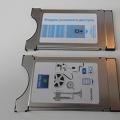 Satellite receiver or satellite TV input ci common interface