Modification of the power supply. Repair of the receiver tricolor GS8300. Alteration of the power supply Tricolor gs 8300 power supply repair
GS 8300 is the first receiver in the line of receivers for Tricolor TV, which supports the MPEG-4 compression format and the DVB-S2 broadcast standard. This is the first receiver to receive over 150 channels. We can say that a new era of receivers for receiving Tricolor TV began with it. It's funny, but it started, like many receivers for Tricolor TV, with problems of a different nature. Either the receiver was activated for a long time, then the card was not seen ...
But. As a result, the stability of the receiver was still raised with new firmware. This material is not about the troubles of the GS 8300 receiver, but about what it consists of. Consider.
We can say that on this receiver the manufacturer got his hands on the production of MPEG-4 DVB-S2 camera receivers. And judging by the number of GS 8300 receivers in the hands of users, this experiment was a success. The GS 8300 receiver is equipped with a removable access card, but there is no access card in the GS 8300M receiver - the chip is sewn into the receiver itself.
The receiver is built on a processor STi5119, 4 MB FLASH memory, only 16 MB RAM - a ridiculous amount compared to the GS 9303 or GS U510. But the class of the receiver is different, because the 8XXX series does not support channels in HD format.
So. Below is a photo of the motherboard of the GS 8300 receiver. Both the general plan and close-ups of individual nodes. Maybe someone will find these photos useful.
GS 8300 - general view of the board

And now different knots close-up


And in the photo below, the power supply capacitor. The power supply fa photo is no longer native, but after replacement. And the capacitor used in it is of better quality than in the original PSU. Although the values of the capacitor itself are the same.

And here is another element. You can unsubscribe in the comments about his appointment. I myself did not delve into this issue.

This is what I got today with a swoop photo review of the stuffing of the receiver for Tricolor TV - GS 8300. That's all for this.
Repair of the receiver tricolor GS8300. Modification of the power supply. A typical malfunction of the gs8300 tricolor receiver is very common and consists in the failure of the power supply. Repairing this power supply is sometimes quite difficult due to the fact that there is no original PWM controller chip. But it can be converted to another available chip 5L0380 with changes in the installation of the power supply. TAGGSM.RU issue partner http://goo.gl/rUoVNb TexRemont - a simple solution to computer problems Many users in the event of a breakdown of a computer, laptop or LCD TV immediately turn to specialists who can repair it all. On the one hand, this is correct, but on the other hand, the cost of even the simplest repair, such as replacing the BIOS battery, for example, will not be minimal. Therefore, for users who are not afraid to pick up a soldering iron and a screwdriver, a special channel was created https://www.youtube.com/user/texremont1. When a laptop or tablet malfunctions, not everyone knows the intricacies of not only repair and the procedure for disassembling devices. On the TexRemont channel you can watch hundreds of videos on this issue. They contain video instructions in which professionals show in detail the features of working with a wide variety of models of laptops, video cards and motherboards from various manufacturers. At the same time, the main problems and ways to solve them that may arise during operation are described. A detailed description of the disassembly of laptops and tablets of various brands from various manufacturers can also be viewed without any problems. Not every person can boast of that. That he knows how to work with such a fairly simple device as a soldering iron, especially a soldering station. Features of using modern infrared stations are described on the TexRemont channel, and at the same time, you can always watch detailed video tutorials of work related to such an important feature as chip reballing, which is the basis of modern precision electronics. Repair of computers and their components is a rather complicated and time-consuming process that requires skills and experience. The TexRemont channel details the main actions in situations where a computer fails at the hardware level. The channel describes in detail the features of upgrading computers, connecting various devices and gadgets. Hundreds of videos will help a novice electronics engineer to choose the right equipment for repairing computer and digital equipment and teach how to work with it. A detailed description of modern soldering and mounting technologies will teach anyone who wants to independently repair laptops and computers. Our partner Youpartnerwsp
The power supply of the Ferex R&D FP09T001 Rev.2 receivers is assembled according to the scheme of a pulsed flyback voltage converter, shown in fig. 12. Input mains AC voltage 190 ... 240 V with a frequency of 50 or 60 Hz through a fusible link F1, a noise suppression filter C1LF1 that prevents the penetration of interference from the source into the network, a current-limiting resistor RT1 and a diode bridge D1-D4 is fed to a smoothing capacitor C5.
GS-8300 satellite receiver power supply circuit
The series resistor RT1 limits the inrush current through the diode bridge D1-D4 while charging the capacitor C5. Varistor RV1 protects the source from overvoltage. When the supply voltage exceeds the permissible value, the resistance of the varistor decreases, the current flowing through it increases and the fuse F1 burns out.
The rectified DC voltage passes through the control unit to the primary winding of the transformer T1. It is switched by a powerful field-effect transistor Q1 controlled by a SHI controller U5. The energy accumulated in the transformer is transferred to the secondary windings and rectified by diodes D5. D7-D9.
To start the power supply when connected to the network, a rectified voltage is used, which comes through the current-limiting resistors R4, R5 to pin 5 of the U5 chip. After starting, voltage appears on the secondary windings of the transformer T1, and the U5 chip is powered by the voltage rectified by the diode D5 through the current-limiting resistor R19.
Stabilization of the output voltages of the power supply is provided by the elements U2 (optocoupler, galvanically decoupling the primary and secondary circuits of the source) and U3 (voltage stabilizer). The nominal values of the output voltages are set by the divider R25R26. When they increase during operation, the transistor in the optocoupler U2 opens, and the SHI controller U5 reduces the duration of the pulses that open the transistor Q1.
As a result, the energy transferred to the secondary circuits is reduced and therefore the output voltages are reduced. A +5 V linear voltage regulator is assembled on a powerful field-effect transistor Q2 and a U4 chip. Its nominal output voltage is set by the divider R35R38. The appearance of the power supply is shown in fig. 13.
Hello, today we will try to fix the Tricolor TV receiver with our own hands. Many faced such a problem when the warranty (usually it is 12 months) ended, and the receiver suddenly failed. A new one is expensive, and in most cases, repairs will not be difficult and will cost a penny, if you are at least a little friends with a soldering iron, the main and most common malfunctions can be easily fixed by yourself. Consider such a repair using the example of another receiver from the Tricolor TV company GS-8300 N. I must say that the device is not of the best quality, and the money that Tricolor TV takes for it, of course, is not worth it. But, nevertheless, the number of subscribers is large and not all of them work for a long time and properly.
Power circuit failure:
The main and most common malfunction of all receivers is a malfunction in the power supply circuit and voltage conversion. Also, the modulator often fails due to a short circuit in the coaxial cable from LNB, although the latest models have good cable short circuit protection, when triggered, the voltage supply to the converter simply stops until the short circuit is eliminated.
And so, our receiver does not show any signs of life, the indicators on the front panel display do not light up, and no juggling of the mains plug from the socket and turning the toggle switch on and off does not help us (at least, this was the case with the device, an example of which is given in this article) . The first thing we do is pull out the plug from the network, and remove the top cover, we need to get to the electronic filling of the device. And here it is important to remember one thing, namely the warranty seal, which we will certainly break if we remove the cover. Therefore, once again make sure that the warranty period has exactly expired, and no one will repair it for you under warranty. If the warranty is still valid, I advise you to take the receiver to a service center and entrust this matter to a specialist.

Opening the cover, we see printed circuit boards with many components interconnected by wire buses. Below are photos describing some of the devices on the board. First of all, we are interested in the power board, it is not difficult to distinguish it by the transformer installed on it, and the supply of the network wire. And the first thing we pay attention to is the fuse. It is usually installed at the beginning of the chain. The fuse will not necessarily have the shape you are used to (a glass capsule with a thin conductor inside), for example, in my case, the fuse is enclosed in a small plastic box, and in order to get directly to the fuse itself, the cover of this box must be removed. This is done very simply, for example with tweezers. Having reached the fuse, we check it with a tester or multimeter for a gap. If the fuse is blown, which by the way happens very often, we go to the radio store, buy the same one, change it and that's it. If this is not the case, we check the details further down the chain. Often the transformer itself fails, we can detect such a malfunction by measuring the voltage on the secondary winding. I must say, not everyone can possibly replace the transformer, if so, then it’s better to take the receiver to the workshop, but if you are confident in your abilities, then go ahead, for example, it won’t be difficult for me.
Receiver inside:


An electrolytic or oxide capacitor at the input often dries up and fails, which is also a malfunction, not everyone can find such a breakdown either, you need to have at least the initial level of a radio amateur. Usually failed capacitors have a yellowish appearance, or a small brown speck on the circuit board at the base of the legs. Also, the serviceability of a capacitor can be determined by comparing its nominal and measured capacitance.
The receiver uses direct current, which is rectified from the AC network using a diode bridge. Problems with the diode bridge also happen. Diodes are very easy to check, the main function of a semiconductor diode is to pass current in one direction, but not in the other. In my case, the transistor of the primary winding of the transformer turned out to be faulty, it is not difficult to find it, usually it has a radiator for heat removal. I determined the malfunction of the transistor by measuring the voltage at its emitter, it was absent there, the primary winding was not powered, respectively, everything else is de-energized. The transistor cost me 28.5 rubles. By replacing it with a soldering iron, I fixed the problem and the receiver is back in working order. I must say such a breakdown is quite rare, usually everything ends with a fuse.
A very common malfunction is a firmware rally. The firmware often flies, the evidence of this is usually the complete freezing of the receiver. In this case, "flashing" will help. I also want to say about another reason for the malfunction, which may arise due to poor-quality installation. Water in cable. If the outer insulation of the cable is broken, then water from atmospheric precipitation can get inside and easily enters the receiver through a hose, sometimes flooding all its insides. The condition of the cable must be monitored throughout the life of the device.
Electronic devices surround us everywhere: on the street, at work, at home. With the rapid growth and availability of satellite television to the general public, a wide range of satellite equipment has appeared for the public. These are satellite receivers, conditional access modules, antennas, converters, etc. Whether we like it or not, sooner or later breakdowns happen to them, which cause us to feel the loss of our favorite thing.
You should not despair - for this there are service centers that you can contact and they will help you bring your equipment back to life.

Equipment breakdowns occur for various reasons - voltage drops, failure of various components, wear and tear of the equipment itself from its venerable age, one can also note the incompetence of the owners themselves, for example, incorrect replacement of software in satellite and cable receivers.
The failure of the power supply is perhaps the most common type of malfunction of digital terminals. It occurs for various reasons: a poor-quality power supply (see photo), poor-quality radio components are used, especially this is de facto in Chinese technology.
This also includes a violation of operation, dust, dirt, as a result of which the thermal regime is not correct (see photo).

The service center is a structural division within the company. He is entrusted not only with the repair and maintenance of products sold by our company, but also with the repair (including warranty) of satellite equipment of other companies. Our clients are not only individuals - users, but also equipment dealers who seek to save their customers from the problems associated with the repair and maintenance of receivers. A flexible policy towards corporate customers allows us to provide proper service and satisfy the interests of all customer groups. This is more than 1000 pieces of equipment per month. Of course, the professionalism of the employees, the equipment of the service center with professional equipment, tools and technical documentation make it possible to carry out such large volumes. Therefore, our service center performs repairs of high complexity: for example, the replacement of processors in BGA packages. The repair takes place as soon as possible.
The supply department, in addition to its main function - the purchase of equipment, also deals with the needs of the service center, purchasing components necessary for repairs. And here it is worth noting that the selection and purchase of components for repairs takes place according to the following criterion: the quality of the parts is in the first place, their price is in the second place, but due to the large volumes of supplies of parts, the price ultimately remains low.
All orders are processed electronically and registered in the database. This makes it easy to track the various stages of the repair process. The work performed is guaranteed.
Of course, unforeseen moments happen - for some reason, repairs are delayed. This usually happens due to the lack of some scarce radio component. Sometimes repairs require a complete replacement of the motherboard, and this repair part is not always available. In this case, we are trying to find some acceptable solution together with the client, taking into account his wishes, combined with our capabilities.
The receiver died after a power surge in the network.
At autopsy, the following were found out of order:
- network capacity C5 - 47µFx400V
- Q1 - CS2N60F
- R8, R11, R13 - 3 ohm each (size 1206)
- R9 - 47 Ohm (1206)
- U1 - it was not possible to determine its type by marking on the case.
According to the table for identification and selection of analogues, the last part was replaced by SG6848 with minimal interference in the factory circuit.
We dismantle: (circled in red in the photo)
-U1
- R8, R11, R13 - 3 ohm (1206)
- R3, R6 (one of them is possible) - 1 MOm (1206)
- C3 - 68nF
- R25 - 3.6 kOhm (0805)
- R26 - 10 kOhm (0805)
Install:
- instead of U1 - SG6848
- instead of R8, R11, R13 - one resistor 1.8 Om x 0.5W (usual output, because I did not find the required value of smd))
- instead of C3 resistor 100 kOm (1206)
- instead of R26 resistor 33 kOhm
- instead of R25, we select a resistor in the range of 10-12 kOm, controlling the voltage of 3V3 at the VD8 cathode. I settled on 11 kOm, U=3.36V (at 10 kOm U=3.28V, at 12 kOm U=3.41V)
Instead of the burned out Q1, SSS4N60B was installed (TO-220F case)

PSU diagram GS-8300

On Telesputnik they posted a power supply diagram. 
There are inaccuracies:
1. The lower terminal of the primary winding must be connected
to the connection point of anode D6 and drain Q1
2. Position designation C2 and C3 is incorrect. C3 must be connected to the 3rd pin
U1, C2 to the 4th pin of U1.
3. Rating C3=68nF
4. There are two capacitors C1 in the diagram
5. Missing C12
6. Primary land is labeled in the same way as secondary land.
7. Missing C8
8. Q2 - MOSFET NTD14N03R
9. Rating C11=2200pF
10. Type D8=SR560
11. The positional designation of U3 and U4 is incorrect - they must be swapped.
12. Rating C5=47µF
If the AV output does not work
Question:
The receiver turns on, there are 18 volts on the LNB. There is no video signal, it gets very hot (does not hold a finger) stv 6419 .. because of it there may not be a video? no other point? (in the sense there is no more video signal from where?) the receiver switches channels ..
Receiver GS 8300N no video and audio signal through scart to TV, channels are switched on the receiver panel.
Solution:
the video signal from the STi5119ALC processor comes in, you can check it with an oscilloscope at a test point opposite the capacitor C117, then it comes to the resistor R87 and is transmitted to the capacitor C129 and then goes to the STV6419 chip, there is no output to R91 from it, the culprit is no 12 volts on the board, respectively, there is no power supply + 12V on the 3rd leg of STV6419, a 12 volt D3 zener diode is faulty near the power connector
There was such an answer: if you use only a composite video signal, most likely you can simply throw it away (replace it with a jumper). Where to put the jumper? if this is the right advice..
Faulty VD3 (VD3 zener diode at 12 V) on the motherboard next to the power connector.
Zener brand and parameters:
Power supply +12V to the 3rd leg STV6419 ...
In a chain: connector XP5 9th leg ---> R81 (300 Om) + zener diode VD3 (12V) = stabilizer + 12V ---> L3 ---> 3rd leg STV6419.
Zener diode analogue:
VD3 STV6419 similar zener diode (SMD) was not found. Set 0.5 watt glass zener diode the size of a diode kd522 . While the flight is normal.
If replacing the zener diode did not help:
After a thunderstorm, 6419 swelled. After the replacement, the image did not appear, but when checking the strapping, two resistors turned out to be open, R91, R95. Replaced it and everything worked.
One more problem:
And yet, instead of 13, 18 Volts, 24V went to the LNB. Needed a replacement DA1 (LM317T). And that's it, the flight is normal
The same situation with the GS-8304 receiver:
After 5 years of work, the GS-8304 suddenly stopped broadcasting, although the indication is working properly.
The zener diode has broken into a short circuit ... Zener brand MMZE5242B...
 Modules for digital television
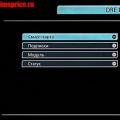 Tricolor TV - receiver software update
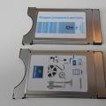 Satellite receiver or satellite TV input ci common interface