4 pin power supply connector. SATA Molex adapter: what is it
The ATX specification requires the power supply to produce three main outputs, +3.3 V (± 0.165 V), +5 V (± 0.25 V) and +12 V (± 0.60 V). Low-power −12 V (± 1.2 V) and 5 VSB (standby) (± 0.25 V) supplies are also required. A −5 V output was originally required because it was supplied on the ISA bus, but it became obsolete with the removal of the ISA bus in modern PCs and has been removed in later versions of the ATX standard.
Originally the motherboard was powered by one 20-pin connector. Current version of ATX12V 2.x power supply provides two connectors for the motherboard: a providing additional power to the CPU, and a main, an extension of the original 20-pin version.
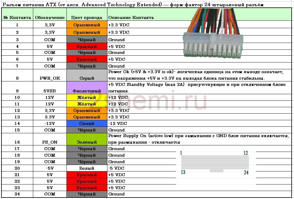
ATX connector pinout
| Pin | Name | Color | Description | |
|---|---|---|---|---|
| 1 | 3.3V | Orange | +3.3 VDC | |
| 2 | 3.3V | Orange | +3.3 VDC | |
| 3 | COM | Black | Ground | |
| 4 | 5V | Red | +5 VDC | |
| 5 | COM | Black | Ground | |
| 6 | 5V | Red | +5 VDC | |
| 7 | COM | Black | Ground | |
| 8 | PWR_OK | Gray | Power Ok is a status signal generated by the power supply to notify the computer that the DC operating voltages are within the ranges required for proper computer operation (+5 VDC when power is Ok) | |
| 9 | 5VSB | Purple |
5 VDC Standby Voltage (max 10mA) 500mA or more typical |
|
| 10 | 12V | Yellow | +12 VDC (may sometimes have a colored stripe to indicate which rail it "s on) | |
| 11 | 3.3V | Orange | +3.3 VDC | |
| 12 | -12V | Blue | -12 VDC | |
| 13 | COM | Black | Ground | |
| 14 | / PS_ON | Green | Power Supply On (active low). Short this pin to GND to switch power supply ON, disconnect from GND to switch OFF. | |
| 15 | COM | Black | Ground | |
| 16 | COM | Black | Ground | |
| 17 | COM | Black | Ground | |
| 18 | -5V | White | -5 VDC (2002 v1.2 made optional, 2004 v2.01 removed from specification) | |
| 19 | 5V | Red | +5 VDC | |
| 20 | 5V | Red | +5 VDC |
/ PS_ON activated by pressing and releasing the power button while the power supply is in standby mode.
Activating / PS_ON turns on the power supply.
In several power supply units pin-12 may be Brown (not Blue), pin-18 may be Blue (not White), and pin-8 may be White (not Gray). In addition, some PSU violate color coding of wires.
Pin 9 (standby) supply 5V even when PSU is turned off. Pin 14 goes from 0 to 3.7 when PSU switch is turned on.
Shorting pin 14 (/ PS_ON) to GND (COM) causes power supply to switch ON and PWR_OK to change to + 5V.
This article promises to be quite explanatory and theoretical. Today we will consider in detail the subject so relevant in our time of technology - an adapter. This will be an adapter SATA Molex("SATA Molex"). In this article you will find answers to your questions, for example, what it is, what it is intended for, what function it performs, and others.
SATA Molex
Let's start with the fact that SATA (sata) is just an abbreviation, but somewhat incomprehensible. In relation to computer technology, the decryption will be as follows - Serial Ata The Acronym. To put it simply and clearly, SATA is a serial interface that appeared in 2003. It replaced the IDE connector (IDE), which was later renamed to PATA (pata) - parallel ATA, since it was a faster connector, involving data transfer at a speed of up to one and a half gigabits per second. This also explains the physical change of the hard drive connector itself, as a result of which a need arose for a special device. Here we are talking specifically about the adapter SATA power supply(SATA). It is needed to connect new hard drives to old computers that do not have such a connector.
Why do you need a SATA Molex adapter ("SATA Molex")?
Today, all modern ones have a Molex connector. Despite this, the SATA Molex adapter itself ("SATA Molex") has relevance and quite high demand to this day. Why? For example, you want to install on your Personal Computer additional equipment in the form of hard drives (or in the form of an additional CD-ROM drive). However, the available free ones are already taken. What will you do in such a situation? The SATA Molex adapter ("SATA Molex") will come to your rescue. 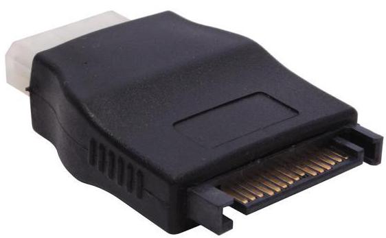
What it is?
In fact, the SATA Molex adapter is the simplest device, which consists of two connectors for connecting to the connectors, interconnected by four lengths of cable. Previously, devices with a Molex connector were powered by four following contacts: + 5V; Earth; Earth; +12. The SATA power connector has fifteen pins. It is divided into five groups and has a sequence of + 3.3V; Earth; + 5V; Earth; + 12V.
There is also a less common SATA Molex adapter ("SATA Molex") for connecting power to a laptop CD-ROM drive. This device has a more compact connector due to the fact that it has only six + 5V contacts (instead of fifteen) and ground.
Pinout
Let's take a closer look at the Molex SATA adapter. The pinout of this device, like the connector itself, is pretty simple.
The first group of contacts in the SATA connector is a voltage of +3.3 volts. This group is not used in the adapter, since the Molex connector does not have such a voltage at all.
The second group of SATA contacts is earth.
The third group of contacts of the connector has a voltage of +5 volts. It should be noted that it is combined with the first contact.
The fourth group of contacts of the connector is ground, it is combined with the third contact of Molex (molex).
The fifth group of contacts of the SATA connector (+12 volts) is combined with the fourth contact of the Molex connector.
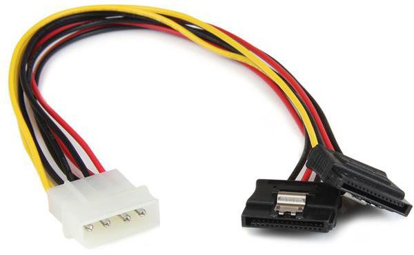
The adapter can be purchased at any computer store or in the radio parts department. These devices have completely different lengths: from a few centimeters to several tens of centimeters. The most common adapters cost around one dollar. Also on sale there are adapters not only one to one. There are adapters from one Molex connector to several SATA connectors. This is very convenient in those cases when your power supply has already run out of all free connectors, while there is one Molex (molex) in the presence and configuration, but you need to turn on several SATA devices. The device already described in the article will help you here.
We provide reference data on color coding and the location of the wires in the sockets and plugs of the PC. The pinout and connection of the wires of the power supply and other main computer modules must be carried out accurately and accurately in order to prevent short circuits during operation. Let's find out what voltage is applied and on which wires.

Color coding
In ordinary PC power supplies, 9 colors are used, denoting the role of wires:
- Black- common wire, also known as ground or GND
- White- voltage -5V
- Blue- voltage -12V
- Yellow- supplies + 12V
- Red- supplies + 5V
- Orange- supplies + 3.3V
- Green- responsible for turning on (PS-ON)
- Gray- POWER-OK (POWERGOOD)
- Purple- standby power supply 5VSB
All computer connectors - name and photo
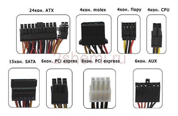
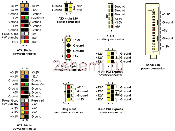
In total, when the power supply unit operates, 8 types of connectors are used, their type and names are shown in the photo. To turn on the AT-ATX power supply, you need to close the GND and PWR SW connectors. It will work as long as they are closed. If you use it separately, put a button on these contacts.
Pinout of the power supply connector wires
Pinout for the sata and esata hard drive power connector

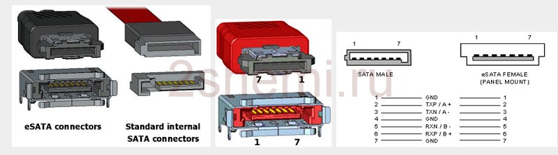
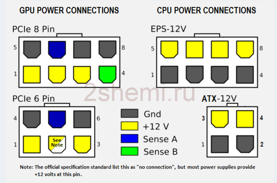
Diagram of the pinout of the power supply pins of the video card
How to get a different voltage from a PSU
| POSITIVE | ZERO | DIFFERENCE |
| +12 | +12 | |
| +5 | -5 | +10 |
| +12 | +3.3 | +8.7 |
| +3.3 | -5 | +8.3 |
| +12 | +5 | +7 |
| +5 | +5 | |
| +3.3 | +3.3 | |
| +5 | +3.3 | +1.7 |
There are situations when the connected device requires such a voltage for its operation that the power supply unit is not capable of producing. In these cases, you have to be perverted. Let's say our additional device (let it be lighting) operates on a voltage of 8.7 volts. We can get it by a combination of wires that give out + 12V and + 3.3V. For convenience, all possible combinations are shown in the table.
2.x, should provide output voltages of ± 5, ± 12, +3.3 Volts, as well as +5 Volts standby (eng. standby).
- The main power circuits are voltages of +3.3, +5 and +12 V. Moreover, the higher the voltage, the more power is transmitted through these circuits. Negative supply voltages (-5 and -12 V) allow small currents and are currently practically not used in modern motherboards.
- The −5 V voltage was used only by the ISA interface of the motherboards. ATX and ATX12V versions prior to 1.2 used pin 20 and a white wire to provide −5 VDC. This voltage (as well as contact and wire) is not mandatory already in version 1.2 and is completely absent in versions 1.3 and later.
- The -12 V voltage is only necessary for the full implementation of the RS-232 serial interface standard using microcircuits without a built-in inverter and voltage multiplier, therefore it is also often absent.
- Standby voltages ± 5, ± 12, +3.3 V are used by the motherboard. For hard drives, optical drives, fans, only +5 and +12 V voltages are used.
- Modern electronic components use a supply voltage no higher than +5 Volts. The most powerful energy consumers, such as a video card, a central processor, and the north bridge are connected through secondary converters located on the motherboard or on the video card, powered by both +5 V and +12 V circuits.
- The +12 V voltage is used to power the most powerful consumers. The separation of the supply voltages into 12 and 5 V is advisable both to reduce the currents along the printed conductors of the boards, and to reduce energy losses at the output rectifier diodes of the power supply.
- The voltage of +3.3 V in the power supply is formed from a voltage of +5 V, and therefore there is a limitation of the total power consumption by ± 5 and +3.3 V.
In most cases, a switching power supply is used, made according to a half-bridge (push-pull) scheme. Power supplies with energy-storing transformers (flyback circuit) are naturally limited in power by the dimensions of the transformer and therefore are used much less often.
Device (circuitry)
Switching computer power supply (ATX) with the cover removed: A - input diode rectifier, visible below inlet filter; B - input smoothing capacitors, the radiator is visible to the right high voltage transistors; C - pulse transformer, to the right you can see the low-voltage radiator diode rectifiers; D - group stabilization choke; E - output filter capacitors
A widespread switching power supply circuit consists of the following parts:
Input circuits
- An input filter that prevents the propagation of impulse noise into the mains. Also, the input filter reduces the inrush current of the charging of electrolytic capacitors when the power supply unit is connected to the network (this can damage the input rectifier bridge).
- In high-quality models - passive (in cheap) or active power corrector (PFC), which reduces the load on the supply network.
- Input rectifier bridge that converts alternating voltage into pulsating DC voltage.
- Capacitor filter that smooths out the ripple of the rectified voltage.
- A separate low-power power supply unit, issuing +5 V standby mat. board and +12 V for powering the converter microcircuit of the UPS itself. Usually it is made in the form of a flyback converter on discrete elements (either with group stabilization of output voltages through an optocoupler plus an adjustable Zener diode TL431 in the OS circuit, or linear stabilizers 7805/7812 at the output) or (in top models) on a TOPSwitch type microcircuit.
- Half-bridge converter on two bipolar transistors
- Converter control circuit and computer protection from over / under supply voltages, usually on a specialized microcircuit (TL494, UC3844, KA5800, SG6105, etc.).
- Pulse high-frequency transformer, which serves to form the required voltage ratings, as well as for galvanic isolation of circuits (input from output, and also, if necessary, output from each other). The peak voltages at the output of the high frequency transformer are proportional to the input supply voltage and are significantly higher than the required output voltage.
- A feedback circuit that maintains a stable voltage at the output of the power supply.
- A PG (Power Good) voltage driver, usually on a separate op amp.
- Output rectifiers. Positive and negative voltages (5 and 12 V) use the same output windings of the transformer, with a different direction of switching on the rectifier diodes. To reduce losses, with a large current consumption, Schottky diodes with a low forward voltage drop are used as rectifiers.
- Output group stabilization choke. The choke smooths out the pulses by storing energy between pulses from the output rectifiers. Its second function is the redistribution of energy between the output voltage circuits. So, if through any channel the current consumption increases, which reduces the voltage in this circuit, the group stabilization choke, like a transformer, will reduce the voltage in other circuits. Chain feedback will detect a decrease in output circuits, increase the total power supply, and restore the required voltage values.
- Output filter capacitors. Output capacitors, together with a group stabilization choke, integrates pulses, thereby obtaining the necessary voltage values that are significantly lower than the voltages from the transformer output
- One (on one line) or several (on several lines, usually +5 and +3.3) 10-25 Ohm pull-up resistors, to ensure safe idle operation.
Advantages such a power supply:
- Simple and time-tested circuitry with a satisfactory quality of output voltage stabilization.
- High efficiency (65-70%). The main losses are due to transients, which last much less time than steady state.
- Small dimensions and weight, due to both less heat generation on the regulating element, and smaller dimensions of the transformer, due to the fact that the latter operates at a higher frequency.
- Less metal consumption, due to which powerful switching power supplies are cheaper than transformer ones, despite the greater complexity
- The ability to connect to the network of a wide range of voltages and frequencies, or even direct current. Thanks to this, it is possible to unify equipment produced for different countries of the world, and therefore to reduce its cost in mass production.
disadvantages half-bridge bipolar transistor power supply:
- When building power electronics circuits, the use of bipolar transistors as key elements reduces the overall efficiency of the device. Controlling bipolar transistors is energy intensive.
More and more computer power supplies are based on more expensive high-power MOSFETs. The circuitry of such computer power supplies is implemented both in the form of half-bridge circuits and flyback converters. To meet the weight and size requirements for computer unit power supply, flyback converters use much higher conversion frequencies (100-150 kHz). - A large number of winding products, individually designed for each type of power supply. Such products reduce the manufacturability of the power supply unit.
- In many cases, insufficient stabilization of the output voltage across the channels. The group stabilization choke does not allow high accuracy to provide voltage values in all channels. More expensive, as well as powerful modern power supplies generate voltages of ± 5 and 3.3 V using secondary converters from the 12V channel.
Standards
AT (deprecated)
In power supplies for computers of the form factor, the power switch breaks the power circuit and is usually placed on the front panel of the case with separate wires; standby power supply with corresponding circuits is absent in principle. However, almost all AT + ATX motherboards had a power supply control output, and power supplies, at the same time, had an input that allowed an AT motherboard to control it (turn it on and off).
The AT power supply connects to the motherboard with two 6-pin connectors that plug into one 12-pin connector on the motherboard. Multi-colored wires go to the connectors from the power supply, and the connection is correct when the contacts of the connectors with black wires converge in the center of the connector motherboard... The pinout of the AT connector on the motherboard is as follows:
| 1 | 2 | 3 | 4 | 5 | 6 | 7 | 8 | 9 | 10 | 11 | 12 |
| - | |||||||||||
| PG | empty | + 12V | -12V | general | general | general | general | -5V | + 5V | + 5V | + 5V |
ATX (modern)
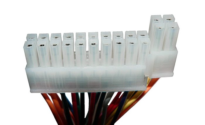
On a 24-pin ATX connector, the last 4 pins can be removable to ensure compatibility with a 20-pin socket on the motherboard
| Output | Tolerance | Minimum | Nominal | Maximum | unit of measurement |
|---|---|---|---|---|---|
| + 12V1DC | ± 5% | +11.40 | +12.00 | +12.60 | Volt |
| + 12V2DC | ± 5% | +11.40 | +12.00 | +12.60 | Volt |
| +5 VDC | ± 5% | +4.75 | +5.00 | +5.25 | Volt |
| +3.3 VDC | ± 5% | +3.14 | +3.30 | +3.47 | Volt |
| −12 VDC | ± 10% | −10.80 | −12.00 | −13.20 | Volt |
| +5 VSB | ± 5% | +4.75 | +5.00 | +5.25 | Volt |
- electromagnetic radiation
- B.Yu. Semenov
- S-ATA.
The requirements for + 5VDC have been increased - now the PSU must deliver a current of at least 12 A (+3.3 VDC - 16.7 A, respectively, but the total power should not exceed 61 W) for a typical 160 W consumption system. An imbalance in the output power was revealed: before the main channel was +5 V, now the requirements for a minimum current of +12 V. for very high currents in this line.
| Output | Minimum | Nominal | Maximum | Unit measurements |
|---|---|---|---|---|
| + 12VDC | 1,0 | 9,0 | 11,0 | Ampere |
| +5 VDC | 0,3 | 12,0 | +5.25 | Ampere |
| +3.3 VDC | 0,5 | 16,7 | Ampere | |
| −12 VDC | 0,0 | 0,3 | Ampere | |
| +5 VSB | 0,0 | 1,5 | 2,0 | Ampere |
| Output | Minimum | Nominal | Maximum | Unit measurements |
|---|---|---|---|---|
| + 12VDC | 1,0 | 13,0 | 15,0 | Ampere |
| +5 VDC | 0,3 | 10,0 | +5.25 | Ampere |
| +3.3 VDC | 0,5 | 16,7 | Ampere | |
| −12 VDC | 0,0 | 0,3 | Ampere | |
| +5 VSB | 0,0 | 1,5 | 2,0 | Ampere |
| Output | Minimum | Nominal | Maximum | Unit measurements |
|---|---|---|---|---|
| + 12VDC | 1,0 | 15,0 | 17,0 | Ampere |
| +5 VDC | 0,3 | 12,0 | Ampere | |
| +3.3 VDC | 0,5 | 12,0 | Ampere | |
| −12 VDC | 0,0 | 0,3 | Ampere | |
| +5 VSB | 0,0 | 2,0 | 2,5 | Ampere |
| Output | Minimum | Nominal | Maximum | Unit measurements |
|---|---|---|---|---|
| + 12VDC | 1,0 | 18,0 | 18,0 | Ampere |
| +5 VDC | 1,0 | 16,0 | 19 | Ampere |
| +3.3 VDC | 0,5 | 12,0 | Ampere | |
| −12 VDC | 0,0 | 0,4 | Ampere | |
| +5 VSB | 0,0 | 2,0 | 2,5 | Ampere |
- to comply with the requirements of the legislation of countries on electromagnetic radiation, in Russia - the requirements of SanPiN 2.2.4.1191-03 2.2.4.1191-03.htm “Electromagnetic fields in industrial conditions, at workplaces. Sanitary and Epidemiological Rules and Regulations "
- B.Yu. Semenov Power electronics: from simple to complex. - M .: SOLOMON-Press, 2005 .-- 415 p. - (Engineer's Library).
- At +12 VDC peak load, the +12 VDC output voltage range can fluctuate by ± 10.
- Minimum voltage level 11.0 VDC during peak load at +12 V2DC.
- The shutter speed in the range is required for the main power connector of the motherboard and the S-ATA power connector.
Power supply / power supply connectors

Pinout of SATA connectors
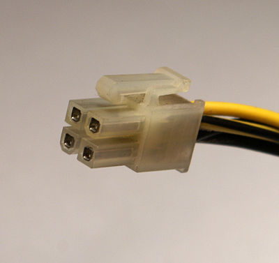
ATX PS 12V (P4 power connector)
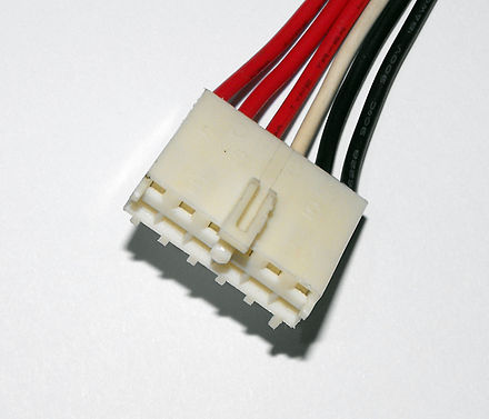
One of two 6-pin AT power connectors
- 20-pin main power connector + 12V1DCV used with the first ATX motherboards, before PCI-Express motherboards.
- 24-pin main power connector + 12V1DC(plug type MOLEX 24 Pin Molex Mini-Fit Jr. PN # 39-01-2240 or equivalent on the side of the PSU with contacts like Molex 44476-1112 (HCS) or equivalent; socket on the motherboard type Molex 44206-0007 or equivalent ) is designed to support motherboards with 75W PCI Express bus. Most motherboards running on ATX12V 2.0 also support ATX v1.x power supplies (4 pins are left unused), for this some manufacturers make a new connector four contacts detachable.
| Colour | Signal | Contact | Contact | Signal | Colour |
|---|---|---|---|---|---|
| Orange | +3.3 V | 1 | 13 | +3.3 V | Orange |
| +3.3 V sense | Brown | ||||
| Orange | +3.3 V | 2 | 14 | −12 V | Blue |
| Black | Earth | 3 | 15 | Earth | Black |
| Red | +5 V | 4 | 16 | Power on | Green |
| Black | Earth | 5 | 17 | Earth | Black |
| Red | +5 V | 6 | 18 | Earth | Black |
| Black | Earth | 7 | 19 | Earth | Black |
| Gray | Power good | 8 | 20 | −5 V | White |
| Purple | +5 VSB | 9 | 21 | +5 V | Red |
| Yellow | +12 V | 10 | 22 | +5 V | Red |
| Yellow | +12 V | 11 | 23 | +5 V | Red |
| Orange | +3.3 V | 12 | 24 | Earth | Black |
|
|||||
| Pin 20 (and white wire) is used to provide −5 VDC in ATX and ATX12V versions up to 1.2. This voltage is not mandatory already in version 1.2 and is completely absent in versions 1.3 and later. | |||||
| In the 20-pin version, the right-hand pins are numbered 11 to 20. | |||||
| Orange +3.3 VDC wire and brown +3.3 V sense wire connected to pin 13 are 18 AWG thick; all others - 22 AWG | |||||
Also on the power supply unit are located:
- 4-pin connector ATX12V(also referred to as P4 power connector) - auxiliary power connector for the processor: MOLEX 39-01-2040 plug or equivalent with Molex 44476-1112 (HCS) pins or equivalent; Mating socket on motherboard type Molex 39-29-9042 or equivalent. 18 AWG wire. In the case of building a high-power system (over 700 W), it expands to EPS12V(eng. Entry-Level Power Supply Specification ) - 8-pin auxiliary power connector for motherboard and processor 12V,
- 4-pin header for floppy drive with AMP pins 171822-4 or equivalent. Wire 20 AWG.
- 4-pin power connector for peripheral type hard disk or optical drive with P-ATA interface: MOLEX 8981-04P plug or equivalent with AMP 61314-1 pins or equivalent. 18 AWG wire.
- 5-pin MOLEX 88751 connectors for connecting power to SATA devices consists of a MOLEX 675820000 housing or equivalent with Molex 675810000 contacts or equivalent.
- 6- or 8-pin power connectors
 Bugs in Singularity?
 Just Cause 2 crashes
 Terraria won't start, what should I do?