Card code in wiegand 26. Wiegand26 protocol on AVR. The principle of data transmission via the Wiegand interface
This is a combination lock for 4 doors with very great features. Most likely you don't need it.
And I had to cut down 4 office doors in one office and so that all issues with the keys were resolved, because. there are constantly hustling a lot of all sorts of people without days off and sleep. Such a controller has already been hung on the entrance doors.
This is the first time I've come across such systems, so I had to dive into all these subtleties as usual. Here I want to write what I encountered, so that you have less work to do later.
This seller has already run out of such a set on eBay, but it is easy to find it by the name of the title.
What tasks should this system solve? Why did you choose it and not other stand-alone combination locks?
This system connects to the network and allows you to monitor in real time open doors, passing personnel, showing photos, register the time of arrival and departure, control the elevator through an additional fee, control one door to control entry and exit by card, monitor the open door, turn on sirens, keep a record of meals on cards in canteens and something else, I can’t remember everything at once.
The controller itself works autonomously from the network, users and settings are loaded into it, and a log of operations is also stored, which sometimes or in real time can be uploaded by the software.
The software uses the ms access file or the network ms sql.
Number of users up to 20000, number of log entries up to 100000.
The software is written in .net, so it's easy to see the source code. In the source you can find the password to the database.
168168
To view the database you need a program
The password to enter the advanced settings menu is 5678.
Login at the first start of the program abc, password 123.
There is a German version of the software, which costs 80 euros. It is already obfuscated and comes with a usb key. It won't start without it.
For my case, I needed a reader with buttons, because. there is staff who will work there permanently, and there are temporary visitors, interns, cleaners. It makes no sense to issue a card to them, it is easier and cheaper to write out a pin and its validity period. Personnel can be combined into groups and subgroups.
A reader without buttons is of course cheaper.
As you can see in the picture, the set consists of several parts. 


The latter are a button for forcibly opening the door from the inside and a 12v power supply for latches. In my case, this is not needed.
Ordinary latches consume 0.7A from 12V. They are designed for short term use.
There are latches with fixation and platoon.
If you need to keep the door open, then there are latches with a small lever. It must be moved to another position and then the latch will not be fixed.
Cocked latches have a pimp near the tongue. A current pulse is applied to such a latch and it is already unlocked. You just need to push the door and it will open. If the door slams shut, the latch will lock it normally. If there is no pimpochka, then the door can only be opened when voltage is applied. All latches of this type are not designed for long-term operation and get very hot.
When installing the latch, put a protective diode on its contacts, because. it is not on the controller board, although there are varistors. But a long wire and a fairly decent current turn the whole thing into an open oscillatory system at a short wave frequency, which can lead to controller glitches and unnecessary sparks on the relay contacts. And so I just connected the contacts to 12v bp and when disconnected, there were no sparks at all.
There are also latches that unlock when no voltage is applied to them. They are put on emergency exits.
There are also magnetic door holders, they are supplied with current and a magnet with a force of 300 kg holds the door. For such holders, 2 power supplies are included.
In my case, the impulse will be 1 second and the power supply in the black box will be enough for this. There is a TO220 transistor on the radiator. There is a circuit for stabilizing the voltage and charging a lead battery. 
Now the theory about the wiegand 26 protocol.
Once a man was sitting in one office and suddenly it dawned on him. Type you can use magnetic cards as a pass instead of shopping. And washed down the interface named after himself.
In fact, of course, it wasn't like that. Wiegand discovered some kind of effect, the essence of which is explained in the video.
If you understand something, then write in the comments in human language.
The interface means there is date0 and date1. Zeros are transmitted on one wire, and ones on the other.
They are transmitted by impulses of attraction of the wire to the ground.
The code was divided into a building code and a map code. 24 bits were allocated for this and 2 more bits on the sides for parity. For those times it was the norm. Now it causes fierce laughter. After all, Wigand does not have two-way communication, there is no encryption and data integrity control, each controller is a separate cable with 5 wires. There is no single standard.
But everyone continues to rivet this rubbish. When I had not yet entered the topic, I thought that they were all connected via rs485. You can imagine my shock when it turned out that I would have to pull a bunch of wires. But it would be possible to pull 4 wires in one cable and make an input for a door sensor and a relay for a lock in each reader. But there are read out with such an interface, and there is rs232. The truth is for some reason more expensive and rare on sale. But you still have to pull the wire from the lock and from the reed switch.


And I have already swindled the fee. 

nxp controller, rom 25 series, real time clock and ethernet phy. Nothing interesting.
This is what the controller board looks like. Wigands also have an output for an LED and a tweeter. This needs to be dealt with separately.
The sys indicator should flash, indicating that the controller is not hung. ID shows the received packet from the reader. The error sometimes lights up if the data has not entered the controller or the network has fallen off.
What is the difference between the reader in terms of compatibility with the controller? As I said above - there is no standard in the data format. Those. if you bring the card, then the whole code is issued immediately. If you dial a pin, then a 4-bit bcd code will be transmitted with each press. The controller must understand the trailing character. In this controller, this is the sequence esc 111 ent. (as an option *111#)
There are more expensive readers that can transmit a pin in this mode, or in 26-bit mode. This is configured in the reader itself. Or in the controller software (not in this one) there are options for setting and interpreting data.
At first I couldn’t set up the software for a pin, it showed an error in the form of an incorrect password. I thought that the typed code was interpreted incorrectly due to the 26 or 34 bit mode, but both of these modes did not affect the error in any way. I contacted the seller and he was also stupid, he said that the reader only works in the card + pin mode, when you need to dial the code and then bring the card. But in the office there is the same controller, though a different reader and just a pin works there.
What to see what the reader transmits in general, I assembled a layout on an arduino, uploaded a test firmware and that's it. 

As you can see, when the buttons are pressed, only 4 bits of the bcd code are transmitted (wiegand mode 6, because there are 2 more parity bits).
If we bring the card, it will give
bits=26
RAW Binary=10100010111000011100110110
This is 4572059, which is what is drawn on the label.
This was the very pitfall. Below I will show this point.
The second stone was the control signal for the LED and the buzzer. By default, the card strip is lit on the reader. If the blue and yellow wires are shorted to ground, the green will light up and beep loudly. With the correct code, there should be a long 1s signal, and with an incorrect one, 4 short ones. But the reader did not respond. Although the voltage level has changed, the trouble is that it does not fall below 2V, and 1.7V is needed to trigger the LED. And with a squeaker it's even worse - it starts to whistle quietly at 1.7v, and in order to squeak loudly and clearly, you need 1.2v at least. The controller does not draw normally to the ground, because. its output is protected by a pair of 470 ohm resistors + another 10k is pulled up to 5v at the input. I had to fence the board on 74245 buffers, then it works clearly. I also want to make 4 outputs to optocouplers for connecting to the alarm inputs of the DVR, so that marks are put on the timeline. In my case, one camera sees 4 doors. But for now, I'm stupid with the circuit and the optocoupler does not open.

I also soldered a transistor for the optocoupler there, but it looks like you need to remove the diodes and put them on the inputs.
All 4 readers must go to one optocoupler, because 4 doors in the office under one chamber.

In addition to the controller, you can additionally buy a board for 1 input and 4 outputs. 
You still ask, why do you need a collective farm with a fee, if there is already a fee with a relay?
There is something it is, only in the software there is no alarm for an incorrect or correct password.
So, where is the software already?
Look for the line there.
software Access controller Software-20171227 16.2 MB Download
This is the most current version.
After starting, we immediately go to tools - extended functions, enter the password 5678.
Configuration tab, check the activate access keypad checkbox. Restart. (The Pwd MGT button appeared on top.)
We press on the left on the big gear of the config, there we select the controllers.

Click search, the controller will be found if it is on the physical network. We add it. Then click on the added controller 2 times, the settings window will open. If you use more than one controller, then there are zones. I have it. One controller controls the entrance doors on the floors, and the second controls the office rooms on the same floor.
Click next and get to the door markings window. 
We call the doors, choose the state of the door. They are controlled by the controller by default or can be permanently open or closed.
The opening time in seconds is also selected. In my case, a short pulse is enough. Here you cannot select the permanent hold open door mode. This is called door as switch. Requires a reed switch and is enabled through a password-protected section.
The attendance checkbox allows you to log the response time. This is useful for the attendance option.
In the menu department we create departments and even subdepartments.
Then we go to the staff.
There is a batch addition of maps and there is a manual addition. In a package, you can use both a usb reader and select a reader on the door.
Then you can give the person a random card from a pack that was scored for a specific department. If there is a desktop usb reader, then put the cursor in the card id field and swipe the card. The program itself will find an entry with this card, click 2 times and drive in the name and surname there. Very comfortably.
Or we drive it in with our hands, but you can also put the cursor in the card id field and read the card. All you need is a reader that emulates a usb keyboard and writes numbers in any text field. I came with the kit, although it was not in the lot. 
What's with the pins?
Here I was transported decently, because. nothing is described in the manual. How many manuals I read - they are all captain's, as if for downs. Nowhere is it written what kind of function this is and why it should be used (meaning not specifically this controller).
Now click the button at the top of Pwd MGT. 


Next, add a new user. In the field of the card we write a pin. Must not start at zero and must not be greater than 65535.
Remove all asterisks in the PIN field. If you need double authorization card + pin, then you need to activate the checkbox in the first tab in the screenshot above.
Standard pin 345678.

The pin is entered like this: esc pin ent or * pin #. On some readers, the asterisk at the beginning is optional.
The pin cannot start from zero, it is ignored.
We distribute access rights further. 

Click allow and upload. The data is loaded into the controller.
The database has been prepared, now we need to upload it to the controller in the form of settings for the controller itself and privileges.
Click the operations button on the left, select all doors, click upload.
Here is an important point. The base can only be uploaded to the controller. If the base is damaged, it cannot be merged back. There is a backup function for this.
From the controller, you can merge transactions or even merge and monitor in real time. 
That's like all. For security, in the controller settings, you can select access from a specific IP address.
For those who want to make their own system and tie a web muzzle, then there is a whole class in php and python.
+17
Add to favorites
Liked the review
+43
+68
Wiegand is a wired communication interface between an ID reader (reader) and a controller. Designed to transfer a unique card code or pin code from the keyboard to the ACS controller.
The principle of data transmission via the Wiegand interface
A three-wire bus is used to connect the controller and the ACS reader via the Wiegand interface. One of the wires is designed to provide power to the reader.
The other two are called Data0 and Data1 and are used directly to transfer information. Transmission is carried out by short pulses unilaterally. Wires Data0 and Data1 are initially energized. A short-term voltage drop on one of them allows you to fix 0 or 1, respectively.
Data transmission via Wiegand interface
The magnitude of the voltage, the time of its fall and the interval between pulses vary depending on the parameters of the controller. In addition to the physical transmission of data, the format of this data is of great importance, which can be identified due to the presence of the Facility code.
Interfaces Wiegand 26…42
Wiegand interfaces are distinguished by numbers in the name, which indicate the number of bits transmitted:
- Wiegand-26- the most common interface, contains 24 bits of code and 2 bits of parity. The disadvantage of this interface is manifested when using an identifier with a longer data series, when several bits are not read, but are cut off, and, therefore, may not be recognized correctly.
The 26-bit format consists of 255 possible Facility codes. Within each facility code, 65,535 unique card numbers can be assigned;
- Wiegand-33- consists of 32 code bits and 1 parity bit;
- Wiegand-34= 32 code bits + 2 parity bits;
- Wiegand-37 – 35+2;
- Wiegand-40- consists of only 40 bits of code;
- Wiegand-42- contains 40 code bits and 2 parity bits.
For successful operation, the reader and the controller must work with the same number of bits. Since, in case of a mismatch, a card with a higher bit depth can be identified erroneously. Modern ACS equipment, as a rule, makes it possible to adjust the bit rate of the Wiegand working interface.
Interfaces Wiegand 4…8
Those access control systems that involve double IDwith card and pin, usually have readers equipped with a numeric keypad. In this case, the dialed code is also transmitted via the Wiegand interface. It can be Wiegand-26: in this case, the data from the keyboard is accumulated and sent to the ACS controller after pressing a special key. As a rule, such a code is limited in length. And there may be interfaces of lower bitness: Wiegand-4, Wiegand-6, Wiegand-8.
They allow each single signal to be transmitted to the controller - thus, the length of the pin code can vary from one character to infinity. However, due to the lack of common standards, the algorithms for working with data for the controller and the reader can vary greatly, which does not always guarantee the compatibility of the keyboard with the controller, even if the Wiegand interface, declared as a working one, has the same bit marking.
Advantages of the Wiegand Interface
- Ease of operation;
- Prevalence;
- Compatibility of devices of different brands;
- Range 100-150 meters.
Disadvantages of the Wiegand Interface
- Lack of line integrity control between the controller and the reader;
- Lack of data encryption and two-way authentication;
- Lack of integrity control of transmitted data;
- One-way data transfer (an additional interface is required for two-way data transfer).
Wiegand interface vulnerability
The Wiegand protocol vulnerability highlights the BLEKey attack method.
BLEKey- a small device costing about 35 US dollars, designed to connect to an RFID reader using data transmission over the Wiegand interface. It is enough to connect to the wires and get power from the reader. After attaching, BLEKey saves information about successful card identification access. Using Bluetooth Low Energy (BLE), the device can sync with a phone app and allows the phone to play the last successful card.
Material of the special project "Without a key"
The special project "Without a key" is an accumulator of information about ACS, converged access and personalization of cards
Articles
Select year: Select month:- OSDP takes data protection to the next level
OSDP is designed for secure data exchange in a protected form with AES-128 encryption. Its physical basis is the RS-485 interface.
- Non-bank applications for bank cards
Modern bank cards have on board microcontrollers with performance and memory resources that far exceed the resources of desktop computers of the late 80s and early 90s. This makes it possible to use bank cards not only as a means of payment, but also in a number of other areas, in particular, in access control and management systems (ACS).
- OSDP Protocol
Over the past decades, the technologies used in access control systems have changed significantly. Readers have gone through an evolutionary path from magnetic stripe devices to Wiegand card readers, then radio frequency readers of close (proximity) and long range, biometric readers appeared. In short-range devices, the technologies that underlie communications between the reader and the identifier have changed in the direction of increasing the security of the information transfer process.
- What you need to know when ordering Mifare cards for ACS
Increasingly, cards of the Mifare 1K standard are used as an access card in ACS. These are contactless smart cards, much more complex and functional than the most popular Em Marin, and you should be very careful when ordering such cards.
- Open Standards Help Improve Access Control Systems
The transition of access control system manufacturers to open standards is leading to a wide range of interoperable solutions with improved features and increased security. Open standards also allow solutions to be easily upgraded as technologies and applications change, giving users confidence in their investment in modern technologies.
- The history of the development of technologies that increase the reliability of the use of identifiers in ACS
Approximately 20 years ago, for the first time in security systems, contactless access cards began to be used instead of the then widely used magnetic stripe cards and Wiegand cards.
- Transfer of ACS from EM MARIN cards to MIFARE® cards. Useful information for the owner of the ACS object.
The vast majority of modern access control systems (ACS) use identifiers operating at a frequency of 125 kHz as a means of access. These are proximity access cards (read only), the most common are EM Marin cards, as well as HID, Indala®.
- Access card selection ACS: MIFARE vs Em Marin
News
Select year: Select month:Quite often, it is required to connect biometric readers to any standard access control system, fire alarm, and others. Anviz equipment supports an easy way to connect and configure to standard systems using the Wiegand protocol.
Supported Wiegand Formats
Anviz biometric terminals with Wiegand output can, upon recognition of a person by biometric parameters, issue a user code to the Wiegand output. The user code can be issued in the following formats:
Card Number (card code)
In this mode, after identifying the user, if he has the right to pass, the code of the user card stored in the Anviz terminal database is transmitted to the controller of the system (ACS) to which we want to connect biometric readers.
Thus, the user can, in accordance with the set rights, traverse the entire system using his card and finger. In this case, the same code of the user's card will be included in the reports of the main system, regardless of whether a regular or biometric reader is used.
Anviz hardware only supports Wiegand 26 protocol by default.
Anviz Wiegand (code Anviz)
When using this mode, after identifying the user, the Anviz biometric terminal transmits a fixed, unknown code via the Wiegand protocol.
This mode is used to organize the safe opening of doors that are external to the office. For example, you can use the SC-011 controller located indoors to work in this mode. In this case, it will not be possible to use the lock control relay located inside the terminal to gain access to the premises.
Fixed width area code
This mode is responsible for transmitting only a part of the Wiegand code via the Wiegand protocol, namely, the device code is transmitted in the form of the first 8 bits of the Wiegand code, usually used as a room code, or an access point code for systems with access organization in accordance with the types of devices used.
Wiegand26
In this mode, Anviz transmits a combination of device code + user code via Wiegand protocol. This mode can be used in systems that do not provide for the use of cards at all. At the same time, since the device code is rarely used, when Anviz equipment is connected in this mode, it is necessary to configure the same device codes to another system.
Connecting Anviz Devices
To connect Anviz biometric equipment to standard ACS systems, time tracking, security and fire alarm devices, perimeter bypass and others, you must do the following:
Connect Wiegand Protocol
When connecting, it is necessary to connect in series the Anviz outputs: wOut0, wOut1 and GND to respectively the terminals wIn0, wIn1, GND of the input interface of the Wiegand protocol of the system to which we are connecting.
Customize software
It is necessary in the Anviz Device Connection Software (comes free with Anviz equipment), set the Wiegand output type according to the selected mode, see the figure below.
The activity of our video surveillance online store covers the entire range of security and protection equipment, which includes:
and much moreCarrying out deliveries throughout Russia, our company delivers goods even to the most remote regions of the country. We try to satisfy the most demanding client.
Active-SB specialists understand the specifics of the operation of security and video surveillance systems not only in Moscow, but also in remote regions with difficult climatic conditions. Our employees will offer you the most suitable options both in terms of functionality and cost, tell you about their capabilities and justify the need to use certain technical systems.
Trading House of Security Systems Aktiv-SB carries out service and warranty maintenance of the equipment sold, acceptance and inspection of goods of inadequate quality, and exchange of faulty equipment.
Our clients are commercial organizations and end users, installation companies and government enterprises. More than 50,000 registered users of the corporate website have access to a constantly updated database of technical documentation, certificates for modern security systems, as well as participate in the affiliate program and special promotions held by the company.
For the convenience of our relationship with customers, we cooperate with installation organizations that are ready to install video surveillance systems of any complexity and will always come to your aid. Therefore, if necessary, you can not only purchase equipment from us, but also, for example, order the installation of video surveillance systems or carry out maintenance of other security systems.
The work of our hypermarket of security systems is based on the principles of honesty, openness and decency. We look to the future with confidence, strive to develop and improve every day.
A way to store binary data on an access card.
Receipt of data by the reader and transmission to the controller of the access control system.
Controller Capabilities for Signal Receiving and Processing
What is Wiegand (Wigand)
Term Wiegand used in various areas related to access control systems, readers and cards. Unfortunately, this term is often used incorrectly, which leads to confusion. Below is a summary.
Wiegand this is:
1. Card-reader communication interface
2. Communication interface reader-controller
3. Electromagnetic signal transmitting data
4. "Standard" binary 26-bit card format
5. Electromagnetic effect
6. Card production technology In our case, only points 2 and 4 are considered.
Note. The term Wiegand also describes some unmentioned card/reader characteristics.
FormatWiegand
By saying "Wiegand format" HID customers sometimes refer to the technology used to encode access cards. But it is worth remembering that the term Wiegand often refers to the standard 26-bit format, characterized by a special arrangement of binary data.
The format describes the meaning of the number, how it is used. Format is notthe number itself.
. The number of bits does not determine the format(except 26-bit format). For example, there are over a hundred 34-bit formats.
The size and position of the data elements on the available number of bits can vary, for example:
o in one 34-bit format, the room code consists of 8 bits and starts from the second bit; o In another 34-bit format, the room code consists of 12 bits and starts from the 21st bit.
Format compatibility is determined by the capabilities of the access control panel. The string of numbers 74955968459 means nothing. If you know that this is a phone in Russia, then it will become clear that 7 is the country code, 495 is the area code, and so on. Decrypt data allows you to use the data. The phone number always looks like this: (xxx) yyy-zzzz because the phone company's equipment only supports this format. Security equipment has similar requirements. Telephone companies strive to ensure that everyone knows the format of phone numbers, as opposed to the security industry, in which the formats are kept secret and changed frequently. The data formats on the 125 kHz proximity and iCLASS cards are identical. This ensures compatibility of controllers working with proximity readers with iCLASS readers and cards.
Standard 26- bit format
The format used when programming the card is determined by the data storage template compatible with the access control panel. All HID transponders (cards, key fobs, tags, etc.) can be programmed in standard 26-bit format.
The standard 26-bit format is open. This means that anyone can purchase such a card, and the description of the format is widely available. The 26-bit format is the industry standard and is available to any HID client. Almost all access control systems can work with the standard 26-bit format. This format evolved from data encoding technology Wiegand. HID's standard 26-bit order code is H10301. In the H10301 format, 255 room codes from 1 to 255 can be encoded. For each room code, 65535 employee codes from 1 to 65535 can be encoded. The total number of possible combinations is 16711425 . There are no restrictions on the use of cards of this format. Its use is not monitored by HID and card duplication is permitted. HID Corporation supports over 1000 other card formats, but they all share the same concept as the 26-bit format. Other card manufacturers also support their own proprietary formats. The H10301 format describes a storage format for binary data. Below is a description of this format.
Open 26-bit Wiegand format
The maximum value of the room code is 255, because if all bits of the room code are 1, in decimal representation the number will be 255. The maximum value of the card code is 65535, because if all bits of the card code are 1, in decimal representation the number will be look like 65535.
Note: The even/odd bits are used to quickly and easily verify that binary data has been transmitted correctly. The format designer chooses whether a particular bit controls odd or even parity. A fixed group of data bits is combined with one data bit, the sum of the values of these bits must be even (or odd).
In the example above, the first (parity) bit is associated with the first 12 bits of data. If the addition of the values of these 12 bits is an odd number, the check bit is set to 1 so that the result of the addition of the 13 bits is even. Similarly, the last 13 bits always add up to an odd number.
Other formats
To better understand the organization of formats, consider two examples of possible card formats.
Note. Since real data formats are closed, we do not consider them as an example.
In the standard 26-bit format, one of the fields is called the room code, the other is called the card code. These fields may be named differently depending on the format. The same name can refer to different data. One possible format might look like this:
HID has assigned the standard 26-bit format code H10301. With it, 225 rooms can be coded - from 1 to 225. Up to 65535 employee codes can correspond to each facility code. More than a thousand other HID formats have a similar concept.
To better understand the principles of organizing map formats, let's turn to examples. In the standard 26-bit format, there are two fields - the facility code and the card code. Their names are different and depend on the format. Suppose some format looks like this:

The first check bit is associated with one subset of data bits, the second check bit is associated with another subset. Both facility code (or room code) and card code fields are defined here, however this format is different from H10301. Therefore, cards where information is encoded in this format may well not be suitable for systems working with H10301.
This format is also possible:

This format has 3 control bits, the position code field (5 bits), personnel number (18 bits) and room code (4 bits). The exact values to be programmed must be checked with the customer. HID has no such information. Customers tend to confuse facility code and location code. There are formats where only one of these fields is present, and there are those where one or none at all. Therefore, when ordering cards, you need to be very careful. In order to avoid repetition of card numbers, it is necessary to know the numbers of the cards used. To configure the access control fields and enter the cards into the system by the integrator, the name of the format of the encoded values of the data fields is required.
One of the possible 36-bit map formats The first check bit is associated with one subset of data bits, the second check bit is associated with another subset. This format also defines the fields room code and card code, but this format is distinctly different from H10301, cards encoded in this format may not be compatible with systems running H10301.
The names of the data fields are determined by the developer of the format, so the names can be anything. Consider another possible format. Rice. 3. One of the possible 30-bit card formats This format has 3 control bits, position code field (5 bits), personnel number (18 bits) and room code (4 bits). In talking with the customer, it is important to find out the exact values to be programmed into the cards. This information is owned by the customer, not by HID.
Please note that customers confuse terms room code(Facility Code) and location code(site code). Some formats have a room code, others have a location code, some have none of these fields, and some have both. Be very careful when ordering cards. To avoid duplication of card numbers, the customer must know the numbers of the cards used.
System integrators also need to know the name of the data format and the encoded values of the data fields in order to set up access control panels and enter cards into the system. Without this information, it is almost impossible to enter a group of cards into the system.
Corporate 1000
HID Corporation has developed a unique format, Corporate 1000, owned by the end user. HID Corporation guarantees the uniqueness of the format and that no duplicate cards of this format will ever be created. To purchase Corporate 1000 format cards, a written confirmation of the right to use this format is required. This allows the customer to fully control the production and distribution of cards of this format. Below are a few more facts about the Corporate 1000 format:
- Customer access control panels must be compatible with the Corporate 1000 format
- All Corporate 1000 formats are 35 bits long, and the formats differ from one another in terms of data placement. For example, the card number may be broken into three or more parts arranged in a bit string. This guarantees the uniqueness of the Corporate 1000.
- At the moment, there are several hundred Corporate 1000 formats, most of the formats are not yet occupied.
- Like other formats, Corporate 1000 are identical on 125 kHz proximity and iCLASS cards.
Note. Neither the card nor the reader take into account the data recording format. The card simply stores and transmits binary data, and the reader receives and converts the data to the Wiegand protocol (or other protocol) standard. Only the controller processes the data according to the data format.
Interface Wiegand reader - controller
An interface defines the way two devices interact. HID readers interact with controllers using standard interfaces:
- Wiegand;
- Serial (RS232, RS422, RS485 Clock-and-Data (second magnetic stripe track) or ABA Let's focus on the Wiegand interface, since this is the most common interface in access control systems.
At the physical level, the Wiegand interface consists of three wires: Data Zero (typically green), Data One (typically white), and Data Return (typically black). When installing a HID reader, these labels must be on the reader and controller. All standard HID readers support the Wiegand interface. Since the data is stored in binary form, the reader receives the data as an electromagnetic signal, converts it to the Wiegand protocol format, and sends the binary string to the controller. Zeros are transmitted on the green wire, ones on the white wire. In the controller, the data is combined and forms a string stored on the card.
Note. The reader does not process or check the read data. This device simply transmits the data stored on the card to the controller using the Wiegand protocol.
Settingcontrollers
The controllers are configured so that cards that do not conform to a certain selected format are not accepted by the system. Almost all controllers can work with the standard 26-bit format (except the manufacturer's proprietary format). Simple controllers can work with one or two formats, more complex ones can support almost all formats after appropriate configuration. Some even create their own formats. After the format is selected, the reader should be configured and cards of this format should be ordered. Cards must be programmed in controller format to work properly. This is the recommended configuration method to make it more difficult for an intruder to misuse a randomly found card. This is due to the fact that complete information about the card format is stored not on the card, but in the controller. Format is not a number, but a way to represent a number. To place an order for HID cards, you need to know the following:
- Format name (for example, H10301.cdf) - currently several hundred different formats are used for encoding cards, there is no default format. The customer must know the name of the required format and communicate it to the corporationHID.
- The data to be encoded, for example, a number in the format H10301.cdf, consists of the first check bit, 8 bits of the room code, 16 bits of the employee code, and the last check bit.
transformation binary , decimal , hexadecimal values
All over the world, it is customary to use decimal notation for calculations, but computers store and process binary data. In binary representation, only the numbers 0 and 1 are used to write a number. Often, for convenience, 4 binary characters are combined into groups, each such group represents one character of the hexadecimal number system. To write hexadecimal characters additionally use bu to youA-F.
Decimal
Binary
Hexadecimal
00000000
00000001
00000010
00000011
00000100
00000101
00000110
00000111
00001000
00001001
00001010
A
00001011
00001100
00001101
D
00001110
00001111
F
In hexadecimal format, only 6 characters are needed to write 24 bits. (1111) (1111) (1111) (1111) (1111) (1111) binary character groups
FFF F F
- Room code 255 looks like FF (15 x16) + 15 = 255.
- Card code 65535 looks like FFFF (15x4096) + (15x256) + (15x16) + 15 = 65535. Hexadecimal number system is used in many controllers due to the compactness and convenience of representing binary data. ProxPro and MaxiProx readers can send data to the controller in hexadecimal format via RS-232 or RS-422 protocol.
 iPhone firmware constantly flies - causes and solutions
 How to restore a Word document if not saved
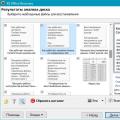 Recovering an Unsaved MS Word Document