Calculation of the maximum length of office telephone optical communication organized using fiber-optic telephones
Page 1
The maximum length of the line connecting the DPS-038 detector with the PIO-017, made with a copper wire with a cross section of 1 5 mm2, is 100 Ohm. To adjust the value of the line resistance in real conditions, trimming resistances specially designed in PIO-17 are used. The line resistance should be 2 ohms. If the line resistance is less than 2 Ohm, then the detector will trigger the relay at a very low rate of rise of the ambient temperature, false alarms are possible. If the line resistance is more than 2 Ohm, then the TEMS developed by the detector will be insufficient for the relay to operate or it is triggered in case of a fire, the thermal power of which significantly exceeds the maximum controlled by these detectors.
The maximum communication line length is 14 km. A dedicated telephone pair serves as a communication line.
The maximum length of the pneumatic remote transmission line can be 300 m with the inner diameter of the transmission pipeline 4 - 6 mm and the inertia of the transmission line 30 - 35 sec.
The question of the maximum length L of the line is reduced to determining the maximum electrical resistance of wires 3, at which the reliable operation of the line continues. Thus, if we assume that the receiver and the transmitter are connected by a copper wire with a diameter of 0 5 mm, then, using a well-known relationship from electrical engineering, we can determine that the length of the line L is 28 km.
Between the control panel and the PU, the maximum communication line length is not more than 60 km (for dedicated physical communication lines), with a radio channel no more than 30 km long.
As an example, in table. 2.4 shows the maximum length of communication lines depending on the type of cable.
In some cases, it is more convenient to make calculations based on the maximum line length at which shutdown is ensured when short-circuited to the case.
Developed by the 70s, underwater communication systems allow a maximum line length of 7200 km with up to 400 semiconductor amplifiers.
On the physical unit of the EM, the following must be determined: the type and characteristics of the data transmission medium; topology of the constituent parts of the data transmission medium; dimensions and design and technological characteristics of SPT elements; the number of transmitters, receivers, repeaters and recovered signals on the mono-channel line; maximum line length between stations; static and dynamic characteristics of receivers, transmitters, couplers and repeaters, as well as encoders-decoders of binary signals into ternary and vice versa.
At the physical level of EM, the following should be determined: the type and characteristics of the data transmission medium; topology of the components of the data transmission medium; dimensions and design and technological characteristics of SPT elements; the number of transmitters, receivers, repeaters and signal couplers on the mono-channel line; maximum line length between stations; static and dynamic characteristics of receivers, transmitters, couplers and repeaters, as well as coders-decoders of binary signals to ternary and vice versa.
Output module discrete signals(MIA) carries out the output to the actuators of the two-position control signals; number of output channels - 8; maximum switching voltage level - 48 V; maximum switched current - 0 2 A; maximum switching frequency - 10 kHz; maximum communication line length - 3 km.
For example, the length of a 35 kV overhead line does not exceed 35 - 40 km. The maximum length of 6 kV lines is 5 - 6 km. If the voltage value is selected or specified, then the cross-section of the wires of the power line is selected according to the load current, and then it is checked what is the voltage loss in the line at such a load current.
When organizing a two-way office telephone optical communication in one optical fiber at one wavelength, it is necessary to use an FOT with optical differential systems based on Y-shaped splitters. Moreover, in each direction A-B and B-A linear the optical signal is transmitted either at a wavelength of λ = 1310 nm, or at a wavelength of λ = 1550 nm.
It is known that the attenuation coefficients at these wavelengths are different:
at λ = 1310 nm, the attenuation coefficient is a = 0.34 dB / km;
at λ = 1550 nm, the attenuation coefficient is a = 0.22 dB / km.
To ensure the maximum communication range of the BOT, it is advisable to use λ = 1550 nm, but this option increases the cost of the BOT. Therefore, WOTs operating at a wavelength of λ = 1310 nm have become more widespread.
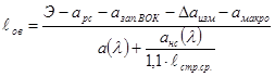
The calculation of the maximum communication range using the VOT is made according to the formula [8]
E is the energy potential of the HOT;
α (λ) [dB / km] - attenuation coefficient optical fiber;
ℓov [km] -maximum length of optical fiber;
ars is the total attenuation of optical detachable connections (OPC) in the optical service communication;
azap.VOK = 3dB, the attenuation margin of the optical cable for the period of operation (approximately 25-30 years);
Δ-measurements [dB] - the error of the measuring device is 0.5 dB;
amakro [dB] is the FOC macrobending loss, which can be neglected if the FOC is properly installed.
a ns (λ) is the average permissible attenuation of welded joints at ESC.
ℓpage Wed - the average length of the construction length of the WOC (4 km)
Energy potential E is calculated by the formula
E = rpr - rprm. min [dB]
Where rpr is the transmission level of the linear optical signal at the output of the BOT;
rprm. min - minimum acceptable level reception at the entrance HERE.
These values are given in technical characteristics HERE.
In modern VOTs, the value of the energy potential is E≈50 ÷ 60 dBm.
Usually, the maximum communication range of the VOT is necessary to know when organizing operational service communication on the mounted ESC.
Then, in the calculation, it is necessary to take into account that in this case, four detachable optical OPC connections are used to connect the OPC to the ODF optical distribution frames of the ESC: two OPCs on one side of the ESC and two OPCs on the opposite side.
The average OPC attenuation is approximately 0.3 dB. Total attenuation ars = 1.2 dB.
The average permissible attenuation of welded joints on ESC a ns (λ) is determined in accordance with the norms for welded joints on ESC.
For a wavelength λ = 1.31 microns, the value a ns (λ) = 0.15 dB, For a wavelength λ = 1.55 microns, the value a ns (λ) = 0.075 dB.
As an example, in the thesis, the maximum communication length for the VOT with the value of the energy potential E = 50 dBm at a wavelength of λ = 1310 nm was calculated.
Substituting the values into the formula, we obtain for the wavelength λ = 1.31 μm the maximum length of the optical fiber
 =
=![]()
![]() , 4 km.
, 4 km.
The maximum length of communication for the FOT is determined by the maximum length of the FOCL route, which is less than the length of the optical fiber
ℓtr.≈ = ![]()
![]() .
.
Maximum flight length
Sometimes it becomes necessary to limit the length of the flight for some cars. For example, if a transport company uses electric vehicles, it is important that such vehicles return to the depot before they are discharged. Using the option, the dispatcher can set the required length of the flight for certain vehicles.
How the "Maximum Flight Distance" option works in VeeRoute
You can set the parameter "Maximum length of the flight" either in the General settings or in the form "A car".
To set the maximum length of a flight for an existing vehicle in Basic Settings, go to "Settings" and select the tab "Cars" in the list "General settings"... Select the required vehicle, set its maximum flight distance in the units of your account (miles or kilometers) and save the changes.
Figure 1. Setting the maximum length of the flight in the General settings
This setting will remain the default for this vehicle until you change the settings.
If you want to set the maximum length of the trip for a car for a certain day or edit the existing value of the maximum distance, click on the car card and open the form "A car"... Set the vehicle to a maximum distance traveled in your account's units (miles or kilometers) and save the changes.
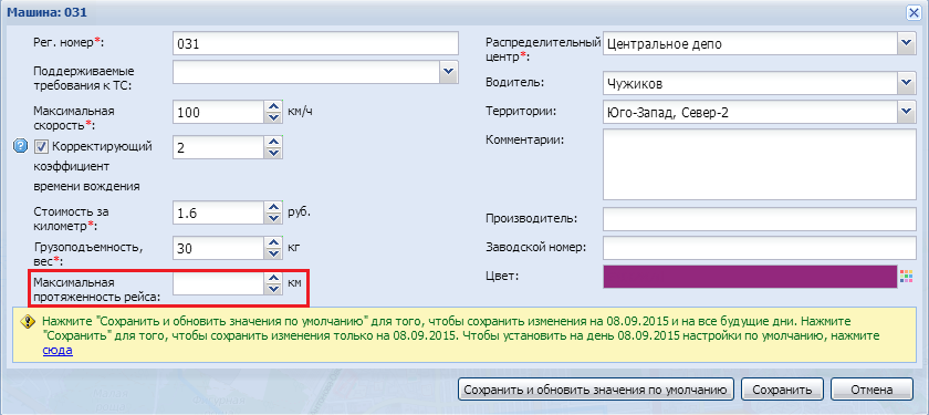
Figure 2. Setting the maximum length of the flight in the "Car" form
When auto-scheduling, VeeRoute will not create flights that exceed the specified maximum distance from start to finish. If the order cannot be scheduled due to exceeding the maximum length of the flight, VeeRoute will indicate the reason why the order is not scheduled - "Exceeded the permissible length of the flight".
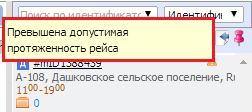
Figure 3. Reason why the order is not scheduled: Exceeded the allowed length of the flight
In manual planning, if the distance of the vehicle exceeds the maximum route distance, VeeRoute will display a warning on the vehicle card and on "tail" flight:
Figure 4. VeeRoute warning about exceeding the maximum distance (car card)
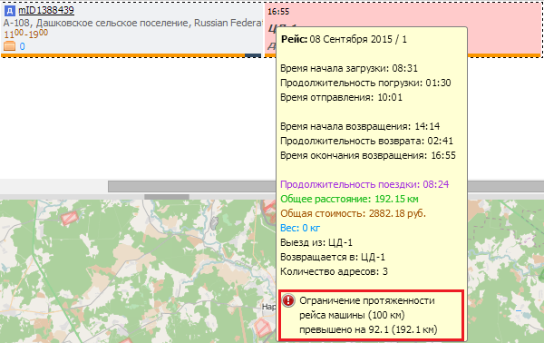
Figure 5. VeeRoute warning about exceeding the maximum length of the flight ("Tail" of the flight)
A rare serious business person, professional programmer or system operator cannot imagine a full-fledged work without using such a powerful, prompt and convenient combination as a regular telephone line, modem and computer network. While the first two components are just the technical side of the new organization of information exchange between users, a computer network is that global idea that unites disparate owners of computers and modems, systematizes and manages chaotically imposed requirements and requests for fast information services, instant processing of commercial offers , services of personal confidential correspondence, etc. etc. Now, in the conditions of information flows that multiply every year, it is almost impossible to imagine a clear interaction between banking structures, trade and intermediary firms, government agencies and other organizations without modern computers and computer networks. Otherwise, it would have to maintain a gigantic staff of paper document processors and couriers, and the reliability and speed of operation of such a system would still be significantly lower than that provided by modem communication and computer networks. But every minute of delay in sending important information messages can result in very tangible monetary losses and image crashes. The evolution of computer technology has resulted in computer networks... A computing network is a complex complex of interconnected and coordinated functioning software and hardware components. Hardware complex - software tools networks can be described by a layered model. At the heart of any network is a hardware layer that includes computers of various classes. The set of computers in the network must correspond to the set of various tasks solved by the network. The second layer is a variety of network equipment required to create local area networks, and communication equipment for communication with global networks. Communication devices play no less important role than computers, which are the main elements of data processing. The third layer is the operating systems that make up the software foundation of the network. When building a network structure, it is important to take into account how effective this operating system can interact with other operating systems on the network, as far as it is able to ensure the security and protection of data, etc. The topmost layer of network tools are various network applications, such as network databases, mail systems, data archiving tools, etc. It is important to know the compatibility of different network applications. Nowadays, the use of computer networks gives the enterprise numerous opportunities. The ultimate goal of using computer networks in an enterprise is to increase the efficiency of its work, which can be expressed, for example, in increasing the profit of the enterprise. If we consider the issue of introducing a LAN into the work of institutions (taking into account the emergence of new opportunities for the enterprise) in more depth, then several more advantages follow from this. The conceptual advantage of distributed systems and, therefore, networks over centralized systems is their ability to perform parallel computations, which increases performance. Such systems have a better performance-to-cost ratio than centralized systems. The next advantage is the sharing of data and devices by users: color printers, plotters, modems, optical disks. Recently, another driving force for network deployment has come to dominate, far more important than the cost savings in sharing costly resources. This motive was the desire to provide network users with prompt access to extensive corporate information. The use of the network leads to improved communication, i.e. to improve the process of information exchange and interaction between employees of the enterprise, as well as its customers and suppliers. Networks reduce the need for businesses to use other forms of communication, such as telephone or mail. Often, computer networks in an enterprise are deployed due to the possibility of organizing e-mail. Of course, computer networks have their own problems (difficulties with compatibility software, problems with transporting messages over communication channels, taking into account ensuring reliability and performance), but the main proof of efficiency is the indisputable fact of their widespread distribution. More and more large networks with hundreds of workstations and dozens of servers appear. 2.Analysis. You need to design a network that has three levels of organization: the department network, the corps network, and the network that connects the corps to each other. Each building has three floors, each floor has several departments, each of which has a certain number of computers. The maximum traffic of institutions is 250 Mbps. There are 4 servers in total. The 1st building is connected to the 2nd and 3rd to the 4th by telephone sewerage, communication between buildings 1,2 and 3,4 is provided by connecting the 1st and 3rd buildings via a wireless line. It is necessary to provide an Internet connection with a speed of 48 Kbps. at a distance of 3 km. In terms of design, maximum performance, information protection, minimum cost are not worth it.Wireless connection.
Among the distinctive properties wireless technologies the most obvious is the possibility of mobility . The impossibility of connecting mobile (otherwise, mobile) subscribers is a fundamentally insurmountable limitation of purely cable networks (i.e. networks using cables both on the network backbones and for connecting subscribers). This limitation applies to any kind of communication - both regular telephone and facsimile communication, and data transmission. Having a technological rather than economic nature, this restriction applies to Russia to the same extent as to all other countries. The use of radio technology made it possible to remove this limitation, causing the rapid development of mobile cellular and trunk networks. Mobile networks are mainly used for voice telephony rather than data transmission, and this trend continues. In some situations, however, mobility is required when transferring data; below we will consider how this opportunity is realized by special means inside a building or on the territory of one institution, i.e. when moving slowly in a confined area. When traveling quickly (in a car) or when traveling over long distances, only radio means of transmitting data at low speeds have been mastered (several times lower than a good modern modem on an ordinary telephone cable gives). In Russia, from such low-speed radio facilities, a mobile cellular telephone with a special cellular modem, as well as radio modems of various types. Another advantage wireless networks is not technological, but purely economic in nature. It concerns the connection of remote subscribers to the network, when it turns out to be economically impractical to pull the cable. These can be either subscribers scattered over a vast sparsely populated (and, as a rule, inaccessible) territory, or subscribers grouped in a remote or hard-to-reach point. In the first case, it is economically inexpedient to lay or suspend subscriber access cables, in the second - trunk cables ("backbone"). Since the telephone channel is busy and there are no free cable routes, it is necessary to use radio channels of terrestrial or satellite communications, which are formed with the help of a transmitter and receiver of radio waves. There are many different types radio channels that differ in both the frequency range used and the channel range. The short, medium, and long wavelength bands, also called AM bands for the type of signal modulation they use, provide long-distance communications, but at a low data rate. The faster channels are those operating in the ultrashort wave bands, which are characterized by frequency modulation, as well as in the ultrahigh frequency bands. For wireless communication between the buildings, it is possible to use radio modems. The layout of the campus buildings is shown in the figure The layout of the town buildings DISTRIBUTION OF STATIONS BY DEPARTMENT
|
3 Selection and justification of the variant of the structural scheme
Following all of the above, we will design a network based on Fast Ethernet and GigabitEthernet technology.Fast Ethernet
Fast Ethernet uses the CSMACD data transmission method - Carrier Sense Multiple Access with Collision Detection. Fast Ethernet uses a packet size of 15160 bytes. In addition, Fast Ethernet imposes a limitation on the distance between connected devices - no more than 100 meters. In order to reduce congestion, Fast Ethernet networks are divided into segments, which are connected using bridges and routers. Today, when building a central backbone connecting servers, switched Fast Ethernet is used. Fast Ethernet switches can be thought of as high-speed multi-port bridges that are able to independently determine which of its ports a packet is addressed to. The switch looks at the packet headers and thus creates a table that determines where this or that subscriber is located with this physical address. This allows you to limit the scope of the package and reduce the chance of overflow by sending it only to the correct port. Only broadcast packets are sent to all ports. The official 803.u standard has established three different specifications for the Fast Ethernet physical layer. The official 803.u standard has established three different specifications for the Fast Ethernet physical layer. 100Base-TX - for a two-pair cable on an unshielded twisted pair UTP category 5 or shielded twisted pair STP Type1; The 100BaseTX standard requires two pairs of UTP or STP. One pair is for transmitting, the other for receiving. Two major cable standards meet these requirements: EIA / TIA-568 UTP Category 5 and STP Type 1 from IBM. In 100BaseTX, it is attractive to provide full duplex mode when working with network servers, as well as the use of only two out of four pairs of an eight-wire cable - the other two pairs remain free and can be used in the future to expand the capabilities of the network. Disadvantages: This cable is more expensive than other 8-core cables and requires punch-through, connectors and patch panels that meet Category 5 requirements. It should be added that full duplex switches must be installed to support full duplex. 100Base-T4 - for a four-pair cable on an unshielded twisted pair UTP category 3, 4 or 5; 100BaseT is an extension of the 10BaseT standard with bandwidths from 10M bps to 100 Mbps. The 100BaseT standard includes a carrier sense multiple access CSMA / CD collision detection protocol. 100BaseT4 uses all four pairs of an eight-wire cable, one for transmitting, one for receiving, and the remaining two for both transmit and receive. Thus, in 100BaseT4, both reception and transmission of data can be carried out in three pairs. Expanding 100 Mbps into three pairs. 100BaseT4 reduces the frequency of the signal, so a lower quality cable is sufficient to transmit it. To implement 100BaseT4 networks, UTP Category 3 and 5 cables are suitable, as well as UTP Category 5 and STP Type 1. In 10BaseT, the distance between the hub and the workstation should not exceed 100 meters. Since the couplers (repeaters) introduce additional delays, the actual operating distance between nodes may be even shorter. The disadvantages are that 100BaseT4 requires all four pairs and that full duplex is not supported by this protocol. 100Base-FX - For multimode fiber optic cable, two fibers are used. Fast Ethernet also includes a standard for multimode fiber with a 62.5 micron core and 125 micron cladding. The 100BaseFX standard is mainly focused on backbones - for connecting Fast Ethernet repeaters within the same building. The traditional advantages of optical fiber are inherent in the 100BaseFX standard: immunity to electromagnetic noise, improved data protection and long distances between network devices.Gigabit Ethernet.
So, due to the increase in information flows, there was a need to increase the transmission speed of the Ethernet standard. The Gigabit Ethernet specification has been proposed and accepted for development by the IEEE 802.3 committee. In May 1996, several major networking equipment manufacturers such as 3Com, Cisco, Bay Networks, Compaq, and Intel formed the Gigabit Ethernet Alliance. Initially, the Alliance included 11 companies. At the beginning of 1998, the Alliance already included more than 100 companies. On June 29, 1998, the IEEE 802.3z standard was adopted. The 802.3z specification describes the use of single-mode and multimode optical fiber (1000Base-LX and 1000Base-FX interface), as well as shielded twisted pair STP Category 5 over distances up to 25 meters (1000Base-CX interface). The 1000Base-CX interface did not gain popularity due to the short segment length. To date, there are no devices with this type of interface. Attempts to increase the segment length encountered an increase in the number of errors during data transmission, which required the development of an error-correcting code. The resulting specification 802.3ab, adopted a year later, defines the use of unshielded twisted pair UTP over distances of up to 100 meters (1000Base-T interface). Gigabit Ethernet uses the same CSMA / CD transfer protocol as its predecessors Ethernet and Fast Ethernet. This protocol defines the maximum segment length. The minimum frame size for CSMA / CD in the 802.3 specification is 64 bytes. It is the minimum frame size that determines the maximum distance between stations. This distance is also called the collision domain diameter. The transmission time of such a frame is 51.2 μs or 512 W (bit time - the time required to transmit one bit). Therefore, the time it takes for the signal to reach the remote node and return back should not exceed 512 W. This time determines the maximum length of the Ethernet network. In the case of Fast Ethernet, the transmission speed increases and the frame transmission time decreases to 5.12 μs. To detect all collisions before the end of the frame broadcast, it is necessary to either increase the frame length or decrease the maximum segment length. Fast Ethernet kept the same minimum frame size as Ethernet. At the same time, compatibility was preserved, but the diameter of the collision domain was significantly reduced. In the case of Gigabit Ethernet, the transmission speed increases tenfold. Accordingly, the transmission time of a packet of the same length is reduced. If you leave the minimum frame size unchanged, the maximum segment length will be reduced to 20 meters. In this case, the equipment is not widely used, as happened with the 1000Base-CX standard. Therefore, it was decided to increase the frame broadcast time to 4096 Wt. This is 8 times more than Fast Ethernet. However, the minimum frame size has been kept the same for compatibility with previous standards. Instead of increasing the frame size, an additional field called "carrier extension" was added to it. Expansion of the carrier does not carry service information. It is designed to fill the canal and increase the collision domain diameter. If the frame size is less than 512 bytes, then the extension field pads it up to 512 bytes. If the frame size exceeds 512 bytes, then the extension field is not added. This solution has one major drawback: most of the channel bandwidth is wasted, especially when transmitting a large number of short frames. Therefore, Nbase Communications proposed a technology called packet bursting. Its meaning is as follows. If the station has several short frames, then the first of them is padded with a carrier expansion field up to 512 bytes and sent. Subsequent frames are sent next with a minimum interframe distance of 96 bytes, which is filled with extension symbols. As a result, no other device can wedge into the queue until all available packets have been transmitted. The maximum size of such a "queue" is 1518 bytes. Therefore, a collision can occur only at the stage of transmission of the first original frame, supplemented by the expansion of the medium. This increases the performance of the network, especially under heavy loads. Manufacturers currently produce a full range of Gigabit Ethernet equipment: network adapters, switches, hubs, converters. Due to the fact that the standard for optical fiber was adopted a year earlier, most of the equipment produced today has interfaces for optical fiber. The main difficulties in using Gigabit Ethernet are associated with differential signal delays in multimode fiber cables. As a result, signal timing faults occur, limiting the maximum distance over which data can be transmitted over Gigabit Ethernet. In Gigabit Ethernet, taking into account 8B / 10B encoding, we get a data transfer rate of 1 Gbps. The Gigabit Ethernet specification initially provided for three transmission media: 1000BaseLX single-mode and multi-mode optical cable with long wavelength 1300 nm laser, for long backbones, for buildings and complexes of buildings. Maximum length multimode cable 550 m, s fiber diameter 62.5 μm, and 550 m s fiber diameter 50 microns. For single mode with maximum length 5 km, s with a fiber diameter of 9 microns. 1000BaseSX multimode fiber optic cable with short wavelength lasers (850 nm) for short low cost trunk lines, maximum length 220 m, s fiber diameter 62.5 μm, and 500 m s fiber diameter 50 microns. 1000BaseCX symmetrical shielded short 150 ohm copper cable for equipment interconnection in control rooms and server rooms. Maximum length 25 m. 1000BaseT for four-pair cables with unshielded twisted pairs of Category 5. This group is named 803.2ab. Maximum length 100 m. Unlike 100Base-T, where only two pairs are used for data transmission, all four pairs are used here. The transmission speed over one pair is 125 Mbps, which gives a total of 500 Mbps. To achieve the speed of 1 Gbps, the technology "double duplex" (dual duplex) was used. Its essence is as follows. Usually, one of the edges of the signal propagating along this line is used to transmit information over one pair. This means that the transmission of information can only go in one direction, that is, one pair can be used only for receiving or transmitting information. Double duplex implies the use of both signal edges, that is, the transmission of information over one pair occurs simultaneously in two directions. Thus, the throughput of one pair increases to 250 Mbps. However, crosstalk caused by the influence of three adjacent pairs in a four-pair cable begins to affect, leading to a significant increase in the number of errors in the receiver and transmitter. To reduce the number of errors, a five-level pulse-amplitude coding scheme PAM-5 was proposed. The widely used four-level coding processes incoming bits in pairs. That is, there are four different combinations: 11, 00, 10, 01. The transmitter can match each pair of bits with its own voltage level of the transmitted signal. This allows the modulation frequency to be reduced from 250 MHz to 125 MHz. The addition of the fifth layer allows you to create code redundancy, as a result of which it becomes possible to correct errors at the reception. This improves the signal-to-noise ratio and reduces the effects of crosstalk. In addition to crosstalk, the four-pair duplex transmission introduces two other parameters not previously defined in any specification. These are Equal Level Far End Crosstalk (ELFEXT) and return loss. ELFEXT evaluates the amount of crosstalk at the opposite end of the line taking attenuation into account. This normalized value, independent of the line length, must be measured on both sides. Return loss characterizes the deviation of the line impedance from the nominal value and is the ratio of the input signal to the reflected signal. Having reviewed the main technologies, let's return to the project. Since in the condition we have a free telephone cable and there are places for laying a cable, as well as the distances on the scale of the town are small, the use of wireless networks is not advisable. Therefore, we will focus on more suitable technologies. After carefully analyzing the information about various technologies, I came to the conclusion that the network of the horizontal and vertical subsystems can be organized on the basis of Fast Ethernet and Gigabit Ethernet technologies. 4. Design of the cable system The cabling system is the foundation of any network. The answer to the high requirements for the quality of the cabling system was structured cabling systems, which are a set of switching elements (cables, connectors, connectors, cross-over panels and cabinets), as well as a technique for their joint use, which allows you to create regular, easily expandable communication structures in computer networks. ... Overview of cable equipment Cables: 1. Twisted pair (UTP / STP, unshielded / shielded twisted pair) is currently the most common medium for signal transmission in local area networks. UTP / STP cables are used in Ethernet, Token Ring and ARCnet networks. They differ by category (depending on the bandwidth) and the type of conductor (flexible or solid). A Category 5 cable typically has eight conductors twisted in pairs (that is, four pairs). All cables consist of 4 pairs (two for file transfer, the other two for voice). RJ-45 plugs and sockets are used to connect cables to equipment. There also appeared cables of category 6, with a frequency of up to 200 MHz, and category 7, with a frequency of up to 600 MHz, which are necessarily shielded. Category 5 twisted pair structured cabling is very flexible in use. Its idea is as follows. For each workplace at least two (three are recommended) four-pair RJ-45 sockets are installed. Each of them is connected with a separate cable of the 5th category to a cross-section or patch - a panel installed in a special room - a server room. Cables from all workplaces are brought into this room, as well as city telephone inputs, dedicated lines for connecting to global networks, etc. In the room, of course, servers are mounted, as well as office PBX, alarm systems and other communication equipment. Due to the fact that the cables from all workplaces are brought into a common panel, any outlet can be used to connect the workplace to a LAN, as well as for telephony, or anything at all. Let's say two outlets in the workplace were connected to a computer and a printer, and the third to a telephone exchange. In the process of work, it became necessary to remove the printer from the workplace and install a second phone instead. There is nothing simpler - the patch cord of the corresponding outlet is disconnected from the hub and switched to a dial-up switch, which will take no more than a few minutes from the network administrator. 2.Fiber optic cables Fiber optic cables are the most promising and fastest-performing signal propagation medium for local networks and telephony. V local area networks fiber optic cables are used for ATM and FDDI protocols. Optical fiber, as its name implies, transmits signals using pulses of light radiation. Semiconductor lasers and LEDs are used as light sources. Fiber optic is classified into single mode and multimode. Singlemode fiber is very thin, with a diameter of about 10 microns. Due to this, a light pulse passing through the fiber is less often reflected from its inner surface, which provides less attenuation. Consequently, single-mode fiber provides longer range without the use of repeaters. The theoretical bandwidth of single-mode fiber is 10 Gbps. Its main disadvantages are high cost and high complexity of installation. Single-mode fiber is used primarily in telephony. Multimode fiber has a larger diameter of 50 or 62.5 microns. This type of fiber is most commonly used in computer networks. The greater attenuation in multimode fiber is due to the higher dispersion of light in it, due to which its throughput is significantly lower - theoretically it is 2.5 Gbit / s. To connect an optical cable with active equipment, special connectors are used. The most commonly used connector types are: SMA is a threaded connector. It was the most common since it was the first to be standardized, but its use is now declining. ST is a bayonet type connector. It is most popular because it provides a more accurate and reliable connection. FC-PC - This connector type is a combination of screw and bayonet connectors. It is not as popular as ST, but it combines the best qualities of SMA and ST connectors. SC - This quick connector is gaining popularity in the market. Patch panel, or connection panel, is a group of RJ-45 outlets mounted on a 19-inch plate. This is the standard size for universal communication racks in which equipment is installed (hubs, servers, uninterruptible power supplies, etc.). On the reverse side of the panel, there are connectors, into which the cables are mounted. Cables with stranded flexible conductors are used as patch cords, that is, connecting cables between the socket and the network board, or between the sockets on the connection panel or distribution frame. Cables with solid conductors - for laying the actual cable system. The installation of connectors and sockets on these cables is completely identical, but usually cables with solid conductors are mounted on the sockets of user workstations, connection panels and cross-sections, and the connectors are installed on flexible connecting cables. Connectors: Typically, the following types of connectors are used: RJ-11 and RJ-12 are six-pin connectors. The former are usually used in telephony general purpose- you can find such a connector on the cords of imported telephones. The second is usually used in telephones designed to work with office mini-automatic telephone exchanges, as well as to connect a cable to ARCnet network cards; RJ-45 is an eight-pin connector typically used to connect a cable to Ethernet network cards or for patch panel connections.Fast Ethernet physical layer standards.
100BASE-TX - for a two-pair cable on unshielded twisted pair UTP category 5 or shielded twisted pair STP Type 1 (max. length is 100m, data transfer rate is 100Mb / s); 100 BASE-T4 - for a four-pair cable on an unshielded twisted pair UTP of category 3, 4 or 5 (the maximum length is 100m, the data transfer rate is 100Mb / s). 100 BASE-Fx - for multimode fiber optic cable, two fibers are used. Of these three technologies, Category 5 unshielded twisted pair (100 Base-TX) is used as the primary cabling system. According to the terms of reference, there is no information protection, therefore, the use of a shielded twisted pair is not required. Also, the project does not require connection of workstations with hubs and hubs with fiber-optic switches. This is due to the fact that twisted pair installation is much cheaper and easier to install than fiber optic installation. When laying the campus subsystem, it is proposed to use a fiber-optic cable (trunk type), since it allows you to reach long distances, has a highly protected shell, which protects it from external influences.Structured cabling system
Following all of the above, we will make a structured cabling system that meets the technical requirements of the course project. The structured cabling system is built hierarchically, with the main backbone and numerous branches from it. A typical hierarchical structure of a structured cabling system includes: horizontal subsystems (within a floor); vertical subsystems (inside the building); a campus subsystem (within the same territory with several buildings). The use of a structured cabling system instead of chaotically laid cables gives the enterprise many advantages: · versatility · increased service life · reduced cost of adding new users and changing their locations · the ability to easily expand the network · provide more efficient service · reliability The structured cabling system includes: 1 . Horizontal subsystem (within a floor); 1.1. Subscriber part; 1.2. Stationary part; 1.3. Switching part; 2. Vertical subsystem (between floors); 3. Subsystem of the campus (within the same territory with several buildings). The horizontal subsystem is characterized by a large number of cable branches, as it must be routed to each user outlet. Therefore, for the cable used in horizontal wiring, increased requirements are imposed on the convenience of making branches, as well as the convenience of laying it indoors. When choosing a cable, the following characteristics are taken into account: bandwidth, distance, physical security, electromagnetic interference immunity, cost. The horizontal subsystem, that is, the storey one, can be divided into three parts: Subscriber part It consists of RJ-45 sockets connected by a patch cord.Stationary part
It is a patch cord that connects sockets with a cabinet with network equipment.Switching part
This is the patch cord between the switch and the outlets on the patch panelVertical subsystem
The vertical subsystem cable that connects the floors of the building must transmit data over long distances and at a faster speed than the horizontal subsystem cable. It consists of longer cable lengths, the number of branches is much less than in the horizontal subsystem. For ease of installation, a Category 5 twisted pair will be used here.Campus subsystem.
The campus subsystem is an interconnection of several buildings; for this subsystem, it is best to build a cable system based on a fiber-optic single-mode cable. The electrical diagram can be found on the drawing of the A1 - 2204 format. 5. The choice of network equipment. Today there are many companies that produce network equipment. The most popular are 3COM, Cisco, Allied Telesyn, ATI, D-Link, and others. The variety of firms makes it difficult to choose equipment, because some firms have been manufacturing for a long time, are prestigious and charge high prices for their products. Others, lesser known, charge lower prices, but the quality can also be lower. The emergence of each new company and its products intensifies competition in the market and leads to lower prices for equipment. Networks are becoming more accessible. 3COM manufactures a full range of networking equipment. It ranks first in the overall supply of equipment for local area networks. CISCO is known in the network products market as a manufacturer of routers and hubs. Workgroup switches have been performing well lately. These firms sell their products at lower prices than other firms. After analyzing the cabling diagram, I need the following equipment: Hubs: 5-port 10/100 base TX - 4 8-port 10/100 base TX - 13 16-port 10/100 base TX - 21 Total 48 switches: 12-port Fast Ethernet 10/100 base TX (UTP / STP) + 8 fiber ports - 5 4 ports 10/100 base TX - 3 8 ports 10/100 base TX 1 12 total cable:· Patch - cord unshielded twisted pair 5 cat. 1m .., Total 613 · patch - cord unshielded twisted pair 5 cat. 5m. Fixed cable UTP 5 category about 7000 meters, patch - wall panel for RJ-45 UTP 5 category 27 pieces Mbps for Internet access (-----), network adapters: For a 1000 Mbps server - 4; for 100 Mbps workstations - 356; for 1000 Mbps workstations - 180 cabinets for network equipment: Cabinet for 600w 600d 12U 22 pieces, cabinet for 600w 600d 24U 3 pieces, cabinet for 600w 600d 36U 1 piece, equipment for connecting to Internet:· Modem .. at 56 Kbps, · Router at 56 Kbps. Having studied the market of network equipment, I found equipment that satisfies the initial task of building a network, the following companies: ... and decided to use it for my project. The brands of the selected equipment will be indicated in the next section. 6.Calculation of the cost of equipment.Equipment name | Firm | Quantity | Price | Total |
|
| Concentrators | |||||
| Switch Hub 816VX 16-port 10 / 100Mb Mini Case | ElNet | 14 | 2316 | 32424 | |
| Switch Hub 824DX-CS 24-port 10 / 100Mb RM | ElNet | 14 | 4398 | 61572 | |
| Switch Hub 808XS 8-port 10 / 100Mb Mini Case | ElNet | 16 | 943 | 15088 | |
| Switch Hub 810CG 10/100 / 1000Mb | ElNet | ||||
Switches |
|||||
| Office Connect Dual Speed Switch 16794 (8 10BASE-T / 100BASE-TX ports) | 3Com | 8 | 3191 | 25528 | |
| SwitchGX2226WM 24 * 10 / 100TX + 2Gigabit port | Compex | 3 | 19806 | 59418 | |
| Network adapters | |||||
| 3C996B-T 10/100/1000 PCI-X Server NIC | 3COM | 154 | 4557 | 701778 | |
| Net 320X-R (Realtek) PCI 10/100 Retail | Eline | 366 | 169 | 61854 | |
| 30 | |||||
Cabinets for network equipment |
|||||
| Wall cabinet 310 (19 ", 17U, 570x815x400, tinted glass door) | IMnet | 12 | 8443 | 101316 | |
Modem |
|||||
| TFM-560R Modem (V.90, PCMCIA, Real Port) | TrendNet | 1 | 1940 | 1940 | |
Router |
|||||
| Cisco 1601 | Cisco | 1 | 32522 | 32522 | |
Cable system |
|||||
| RJ-45 socket 5 cat. | -- | 539 | 54 | 29106 | |
| Cable, twisted pair UTP 5, m | -- | 7000 | 6 | 42000 | |
| Fiber optic cable | -- | ||||
| Patch cord UTP 5, 3m | -- | 599 | 36 | 21564 | |
| Patch panel 19 ”, 12xRJ-45 UTP 5 | -- | 12 | 726 | 8712 | |
| Total: | 1216174 | ||||
| Pos. designation | Name | Number |
| A1, A2. A12 | Wall cabinet with network equipment 600w 600d 12u | 12 |
| X1..X539 | RJ-45 socket | 539 |
| A1 | 4 | |
| A2 | 2 | |
| A2 | 2 | |
| A3 | ElNet Switch Hub 816VX 16-port 10 / 100Mb Mini Case | 2 |
| A3 | ElNet Switch Hub 808XS 8-port 10 / 100Mb Mini Case | 2 |
| A4 | ElNet Switch Hub 824DX-CS 24-port 10 / 100Mb RM | 4 |
| A5 | ElNet Switch Hub 808XS 8-port 10 / 100Mb Mini Case | 4 |
| A6 | ElNet Switch Hub 816VX 16-port 10 / 100Mb Mini Case | 2 |
| A6 | ElNet Switch Hub 824DX-CS 24-port 10 / 100Mb RM | 2 |
| A7 | ElNet Switch Hub 808XS 8-port 10 / 100Mb Mini Case | 4 |
| A8 | ElNet Switch Hub 816VX 16-port 10 / 100Mb Mini Case | 2 |
| A8 | ElNet Switch Hub 824DX-CS 24-port 10 / 100Mb RM | 2 |
| A9 | ElNet Switch Hub 808XS 8-port 10 / 100Mb Mini Case | 2 |
| A9 | ElNet Switch Hub 824DX-CS 24-port 10 / 100Mb RM | 2 |
| A10 | ElNet Switch Hub 816VX 16-port 10 / 100Mb Mini Case | 2 |
| A10 | ElNet Switch Hub 824DX-CS 24-port 10 / 100Mb RM | 2 |
| A11 | ElNet Switch Hub 808XS 8-port 10 / 100Mb Mini Case | 2 |
| A11 | ElNet Switch Hub 816VX 16-port 10 / 100Mb Mini Case | 2 |
| A12 | ElNet Switch Hub 810CG 10/100 / 1000Mb 8 + 1Gigabit + 1ext Port Switch (Desktop metal case) | 4 |
| A1, A2, A4, A5, A7, A8, A10, A11 | 3Com Office Connect Dual Speed Switch 16794 (8 10BASE-T / 100BASE-TX ports) | 8 |
| A3, A6, A9 | Compex Switch SGX2226WM 24 * 10 / 100TX + 2Gigabit port | 3 |
| A1, A2, A4, A5, A6, A7, A8, A9 | Eline-Net 320X-R (Realtek) PCI 10/100 Retail | 366 |
| A3 | FastEthernet 320X-R FullDuplex PCI 10/100 | 30 |
| A12 | 3COM 3C996B-T 10/100/1000 PCI-X Server NIC | 154 |
| A12 | Cisco 1601 Router | 1 |
| A12 | TrendNet TFM-560R Modem (V.90, PCMCIA, Real Port) | 1 |
| A3, A12 | Compex WP11A-E Wireless Access Point (2.4GHz, IEEE802.11b, 11Mbps, Bridging) | 2 |
| A1, A2.A12 | Patch panel UTP, 16 RJ45 ports, 5e, 19 ", 1U | 12 |
While preparing for an article with tricky questions, I came across an interesting question - where did the 100 meter limit on the length of the Ethernet segment come from. I had to dive deeply into the physics and logic of processes to get closer to understanding. It is often said that over long cable lengths, attenuation begins and the data is distorted. And, in general, this is true. But there are other reasons for this as well. Let's try to consider them in this article.
CSMA / CD
The reason lies in CSMA / CD technology - Carrier Sense Multiple Access with Collision Detection... If suddenly someone does not know, then this is when we have one bus (one data transmission medium), to which several stations are connected ( Multiple Access). Each station monitors the state of the bus - is there a signal from another station ( Carrier Sense). If suddenly two devices began to transmit at the same time, then both of them should detect it ( Collision detection). Yes, this is all about half-duplex networks. Therefore, if your gaze is focused exclusively on the bright 10-gigabit future, this article is not for you. First of all, I want everyone to understand that the transmission rate of the signal in the medium is in no way dependent on the applied standard. Whether in Ethernet (10Mb / s) or in 10Gbit Ethernet, the speed of pulse propagation in a copper cable is about 2/3 the speed of light. How cool they wrote in one holivar thread: you can speak quickly or slowly, but the speed of sound does not change from this. Now let's turn to the essence of CSMA / CD. In modern networks, collisions are excluded, because we no longer have a common bus and almost always all devices work in full duplex mode. That is, we have only two nodes at the end of one cable and separate pairs for receiving and transmitting. Therefore, the CSMA / CD mechanism is no longer present in 10Gbit Ethernet. However, it will be useful to consider it, just like, for example, to study RIP, which, it seems, is no longer needed by anyone, but perfectly illustrates the principle of operation of distance vector routing protocols. So, let's assume that we have 3 devices connected to the common bus. PC 1 starts transmitting data to PC3 (triggered a pulse to the bus). Of course, in the common bus, the signal will go not only to PC3, but to everyone. PK2 would also like to transmit, but sees excitement in the cable and expects. When the signal from PC1 to PC3 has passed, PC2 can start transmitting.
This is an example of how Carrier Sense works. PC2 does not transmit while it sees a signal on the line. Now the situation is different. PC1 started transmitting data to PC3. And the signal did not have time to reach PK2, he also decided to start transmitting. Somewhere in the middle, the signals crossed and deteriorated. PC1 and PC2 received a crumpled signal and realized that this piece of data must be sent again. Each station randomly selects a waiting period so that it does not start sending again at the same time.
This is an example of how Collision Detection works. To prevent one station from occupying the bus, there is a 96-bit (12 byte) gap between frames, which is called the Inter Frame Gap (IFG). That is, for example, PC1 transmitted a frame, then it waits for some time (the time it would take it to transmit 96 bits). And sends the next one, etc. If PC2 wants to transmit, then it will do it just in this interval. Also PK3 and so on in turn. The same rule works in the case when you do not have a common bus, but one cable, where two stations are connected to two ends, and they transmit data in half-duplex mode. That is, only one of them can transmit data at a time. Transmits PC2, as soon as the line is free, transmits to PC1, the line is free - transmits to PC2, and so on. That is, there is no clear time synchronization, as, for example, in TDD, when certain transmission gaps are allocated for each end. Thus, a more flexible use of the bandwidth is achieved: If PC1 does not want to transmit anything, then PC2 will not be idle while waiting for its turn.
Problem
What if you imagine such an awkward situation? 
That is, PC1 has finished transferring its portion of data, but it has not yet reached PC2. The latter does not see the signal on the line and starts transmitting. Bam! Somewhere in the middle of an accident. The data went wrong, the signal reached PC 1 and PC2. But, pay attention to the difference - PC2 realized that there was a collision and stopped transmitting data, but PC1 did not understand anything - his transmission had already ended. In fact, he just received the broken data, and as it were, he completed his task of transmitting the frame. But the data was actually lost - PC3 also received a signal distorted by the collision. Somewhere later, much higher up the OSI steps, TCP will notice the absence of data and re-request this information. But imagine how much time will be wasted?
By the way, when the number of CRC errors on your interfaces is growing - this is a sure sign of collisions - broken frames come. This means, most likely, the mode of operation of the interfaces at different ends has not been agreed.
It is precisely to exclude such a situation that one condition was introduced in Ethernet: at the moment when the first bit of data is received on the farthest side of the bus, the station does not yet have to transmit its last bit. That is, the frame should, as it were, stretch over the entire length of the bus. This is the most common description, but in fact it sounds somewhat different: if a collision occurred at the farthest part of the bus from the sender, then information about this collision must reach the sender even before he transmitted his last bit. And this is a 2-fold difference, by the way, in comparison with the first given condition. This ensures that even if a collision occurs, all participants will be unambiguously in the know. And this is very cool. But how can this be achieved? And here we come close to the question of the length of the segment. But before giving an answer to the question about the length, you have to plunge a little into the theory of networks and first introduce the concept of bit time (the term "bit time" did not catch on). This value means how long it takes for the interface to fire 1 bit on Wednesday. That is, if Fast Ethernet sends 100,000,000 bits per second to the cable, then bit time is 1b / 100,000,000 b / s = 10 ^ -8 s or 10 nanoseconds. Every 10 nanoseconds a Fast Ethernet port can send one bit on a Wednesday. In comparison, Gigabit Ethernet sends 1 bit every nanosecond, older dial-up modems could send 1 bit every 18 microseconds. The rapid-fire Metal Storm MK5 is theoretically capable of firing one bullet every 60 microseconds. The Kalashnikov machine gun fires 1 bullet every 100 milliseconds.
If we talk about IFG, then the station must pause exactly 96 bit times before sending each frame. Fast Ethernet, for example, should wait 960 nanoseconds (0.96 microseconds), and Gbit Ethernet 96 nanoseconds
So, to fulfill the condition, the concept of a quantum or Slot time is introduced - the minimum size of a data block that can be transmitted over the network to Ethernet. And it is this quantum that should extend over the entire segment. For Ethernet and Fast Ethernet, the minimum size is selected - 64 bytes - 512 bits. To transmit it, the FE port will need 10 ns * 512 = 5120 ns or 5.12 μs.
Hence the 64-byte limit on the minimum Ethernet frame size.
That is, a 64-byte data block will have 5.12 μs to travel along the bus and return to the sender in case of a collision. Let's try to calculate the distance in the forehead: (5.12 * 10 ^ -6) * (2/3 * 3 * 10 ^ 8) / 2 = 512 meters. Let me explain the formula: travel time (5.12 μs converted into seconds) * 2/3 the speed of light (the speed of propagation of a signal in a copper medium in m / s) and divide by 2 - in order to foresee the worst case of collision when the signal has to go all the way back to the sender. It seems that the figure is familiar - 500 meters, but the problem is that the limitation for Fast Ethernet is 100 meters to the hub (200 to the farthest station). This is where delays on hubs and repeaters come into play. They say that they are all calculated and taken into account in the final formula, but the traces are lost, no matter how much I tried to find this calculation formula with a result of 100 meters, I could not find it. As a result, it is known what caused the limitation, but not where the number 100 came from.
Gigabit Ethernet
When developing Gbit Ethernet, a very important question arose - the transmission time of one bit was already 1 ns, and the transmission of one piece of data already took only 0.512 μs. Even when calculating in the forehead, my formula, without taking into account delays, turns out to be a length of 50 meters (and 20 meters, taking these values into account). Very little, and therefore it was decided, instead of reducing the distance (as was the case with the Ethernet-> Fast Ethernet transition), to increase the minimum data size to 512 bytes - 4096 bits. The transmission time for such a portion of data remained approximately the same - 4 seconds versus 5. There is, of course, another moment that it is not always possible to dial this size - 4 KB of data, therefore, at the end of the frame, after the FCS field, the missing amount of data is added. Considering that we long ago abandoned the common bus, we have a separate environment for receiving and transmitting, and there are no collisions as such, it all looks like crutches. Therefore, in the 10 Gbit Ethernet standard, the CSMA / CD mechanism was abandoned altogether.
Overcoming Length Limitations
So, all of the above was for legacy half-duplex common bus networks. How does this relate to the present moment, you ask? Can we pull kilometers of UTP or can't we? Unfortunately, the 100-meter limit has a different nature. Even at 120 meters with a regular cable, in most cases, many switches will not be able to pick up the link. This is due to both the power of the switch ports and the quality of the cable. The point is in attenuation, and in interference, and in signal distortion during transmission. Ordinary twisted pair is susceptible to electromagnetic interference and does not guarantee protection transmitted information... But first of all, let's look at attenuation. Our typical UTP coil has a minimum of 27 turns per meter and transmits data at a frequency of 100 MHz. The so-called linear attenuation is the attenuation of the signal at each meter of the medium. According to the standards, the attenuation should not exceed 24 dB. On average, this value is about 22 dB for a regular UTP cable, which means the attenuation of the original signal by 158 times. It turns out that the attenuation of 1 dB occurs every 4.5 meters. If we take a cable length of 150 meters, then the attenuation is already about 33 dB and the original signal will decrease 1995 times. Which is already very important. Plus to this is added the mutual influence of the pairs - crosstalk. This is the name of the process when interference occurs in parallel conductors, that is, part of the energy is spent on exciting current in a neighboring cable. We take into account the possible interference from power cables that can pass nearby, and the limitation of 100 meters becomes completely logical.
Why then was there no such limitation in coaxial networks? The fact is that the attenuation in the cable depends on the resistance / section of the cable and the frequency. Recall now that thick Ethernet uses a 2.17mm core cable. Plus Ethernet on a coaxial cable worked at a frequency of 10 MHz. And the higher the frequency, the higher the attenuation. Why do you think the analog radio signal is transmitted to the antennas not through such a convenient coil, but through thick feeders? By the way, the word Base in Ethernet standards means Baseband and says that only one device can transmit data at a time through the medium, no modulation / multiplexing is used. In contrast, Broadband imposes several different signals on one carrier, and on the other hand, each separate signal from the carrier is extracted.
In fact, given that attenuation is due to the characteristics and quality of the cable, significantly more joyful results can be achieved by using a more suitable one. For example, with the help of the P-296 or P-270 cable, even a three-hundred-meter line can be overcome. Of course, this is 100 MB / s in full duplex. For gigabit, there are already other requirements. And in general, the higher the transmission speed, the more parameters have to be taken into account, in fact, therefore, in 10Gbit Ethernet, copper medium is only nominally supported, and preference is given to optics.
Results and links
In general, summing up all of the above, the figure of 100 meters is with a good margin that guarantees work even in half-duplex on the cable. best quality... It is caused by attenuation and operation of the CSMA / CD mechanism. Data used in the article.
 Differences Between GPT and MBR Partition Structures
 Wipe Internet explorer clean
 Windows updates are downloaded but not installed