Connecting GSM module SIM800L to Arduino. GSM GPRS SIM800L MicroSIM module with Sim800l antenna connect to arduino
ESP8266 became real news last year for everyone involved in the creation of devices on Arduino. A cheap microcontroller, with capabilities that exceed its expensive counterpart, and at the same time compatible with AT +.
Arduino did not go overboard, and now this module officially added to the lists supported by the board, and accordingly, more and more users will join the Chinese mk for wi-fi connection... But it happens that in the system it is necessary to track the location of the module, for which one esp8266 board will not be enough. This is where esp8266 sim800l comes in handy.
Smart homes and a lot of crafts require notification of the board's location, whether it be a remote door or a regular tracker. Here is just a short list of the crafts you can create by combining the esp8266 sim800:
- Smart House. Almost any smart home technology can be tuned to specific patterns when an object is approached. But why install motion sensors if you can simply attach a sim800 to a wi-fi board, sew a micron with a battery into some piece of clothing (fortunately, a lot of energy is not required) and automatically turn on the light or open the door when the user approaches.
- Various tracking devices. We are not talking about illegal bugs and other devices that violate your right to privacy. However, the mk can work separately from the arduino, and if you attach a sim800 to it, the overall dimensions of the device will not exceed a matchbox. Just wrap everything in a metal case and attach to the keys as a keyring. From now on, finding a smartphone, keys and even your car in the parking lot will be much easier.
- Robotics and related areas. Here you can talk for a long time about the development of modern virtual intelligence and neural networks, but often there are not enough sensors to create a map of the area and navigate in it. And if you are doing something like that, then the gps module will come in handy. It is especially useful when paired with drones.
When you decide on the ultimate goal of the project, you should understand the nuances of the question. Connecting devices to the above microcontroller is the same as for standard Arduino boards, the only difference is in the number of available pins. The GPS tracker requires 3.7 to 4.2 volts to operate, in contrast to the standard 5 volts issued by the microcontroller. This should be taken into account when constructing the circuit board and the auxiliary power supplies must be selected accordingly. Or install transformers and resistors, depending on what else you will connect to the final system.
By registering in the network, the module will need approximately 2A, but this is its peak consumption and in the future the required current will decrease to 1-1.2 A.
As soon as you connect the tracker to the system, you will need to start it and send the first commands, AT and AT + are best suited. Only after these actions will the module finally start sending data and responding to your requests, so do not worry if you connected it, the diode blinks, but there are no reactions to scripts. You just need to activate Sim800i the first time you use it for it to register online.
Also, you should not consider Sim800i as an alternative to ESP8266, which is what many users sin on on the forums. If you have come across such statements, you can safely say that the author has never worked with arduino in his life. First of all, it makes no sense to compare the auxiliary board and the microcontroller. Not to mention the fact that one of the devices is designed to coordinate, send and receive requests for wireless internet and the second is a GSM GPRS module. Accordingly, they are good addition to each other, but not an alternative.
Connection diagram sim800l to esp8266
The pinout is more than standard. Connect the pin with power to a source capable of delivering voltage in the range of 3.7-4.2 Volts, or to a transformer. TX goes to RX pin and vice versa. As soon as you perform the soldering and decide to test the operation of the module by connecting the power supply, the diodes will signal the correct connection. Then it remains to activate the module according to the method described above, and you will be able to use AT commands for control. If you want to load an auxiliary library or some weighty media, you should familiarize yourself with connecting a memory card to the Arduino system.

First, let's test the port speed and module information by using "AT + IPR?" and "AT + CPAS" respectively. If everything is in order and the information is displayed without errors, then you can continue checking and test the signal level, as well as the operators that the module can see.
Most importantly, Sim800i allows you to call the specified numbers and receive calls, moreover, using the basic libraries.
It also opens up scope for the use of systems with its participation. If you want to write a specific script that launches something by incoming call, then keep in mind that the module reacts to it with the phrase "RING" in the command line.
Such functionality allows you to create hundreds of autonomous control systems, up to the fact that instead of fingerprints or key cards, you can open the door by calling a certain number. But, of course, for a good level of protection, it is worth registering a white list of numbers.
An example of the implementation of connecting a gsm module sim800l to mk esp8266
After connecting and soldering on the above pins, the module should start blinking. As soon as there is authentication in the network, the diodes will blink less often.
If a decrease in the frequency of light signals did not occur, then it is worth, using AT commands, to make sure whether the sim800I network at all accepted your mobile operator and if there is no mistake. Also check the correct pinout and how the SIM card with the antenna is installed, there may be an error in them.
And, of course, bring the system closer to the window, if you are in a multi-storey building, it is quite possible that it simply cannot pick up the signal.
It is easy to connect a GSM / GPRS module based on SIM800L by yourself. Follow several steps and use the modern compact element for your own purposes.
SimCom Corporation offers its users a compact GSM / GPRS module based on SIM800L. The built-in connector allows you to improve the signal. You can also use the antenna that comes with this modular system.
GSM / GPRS module SIM800L - description
Detailed description:
- The module is powered by external sources or through DC-DC converting systems
- The supply range should be between 3.7V - 4.2V. It is worth noting that 5V from Arduino is dangerous for the module's operation, as it will lead to a breakdown, and 3.3V will help to respond to user commands, but there will be no network connection
- Control is via the UART, but a voltage divider is used for Rx and Tx so that no load on the board is made.
- Low power consumption of the SIM800L module allows it to be successfully used for equipment with battery power
- When power is applied, the module immediately starts searching for a network. When it is found, the LED starts to give a signal, blinking slowly. The absence of a network is indicated by the same LED, but with the help of a fast blinking of the light
- The module supports micro SIM card 1.8V and 3V

GSM / GPRS module SIM800L - connection
To connect, in addition to the module itself, the converter and the Arduino UNO R3 controller, you will need USB cable, 12V battery and connecting wires. Follow these steps:
- First, supply power to the system from the battery via DC-DC: from the "minus" voltage should go to the arduino to "GND", from "GND" to the converter element to "minus" at the input
- Connection must be made after you configure the module, setting the output voltage in the acceptable range (3.7V - 4.2V)
- Connect all contacts that come out of the converter to SIM800L, observing the polarity
- Connect TX and RX contacts on the module with the 2nd and 3rd digital contacts on the arduino, respectively
Important: If you need to connect two or three modules to the arduino, then use other codes, writing them in the sketch via SoftwareSerial.
The following video clearly shows how to connect the SIM800L module to the Arduino.
Video: Connecting GSM module SIM800L to Arduino
SIM800L V2.0 GSM / GPRS is a quad-band GSM / GPRS module compatible with Arduino. The module is used to implement GSM (calls and SMS) and GPRS functions. The advantage of this module is the TTL interface, which has a voltage of 5V, which allows it to be directly connected to an Arduino or any other system with a 5V supply voltage. Most GSM / GPRS modules on the market require regulator or level conversion connections, while in SIM800L V.2 GSM / GPRS does not require additional interface level conversion circuits.
Here is an example of a project using SIM800L V.2 GSM / GPRS. The point of the project is to control switches using an SMS controller. You can easily turn most items on and off. household appliances in the house, such as a llama, a fan, and so on.
Characteristics of the SIM800L V.2 GSM / GPRS module
Below are all specifications SIM800L V.2 GSM / GPRS module:- TTL serial interface compatible with 3.3V and 5V Arduino compatible microcontrollers.
- The SIM800L module has a TTL serial interface.
- Antenna plug.
- Network support: four bands 850/900/1800/1900 MHz, capable of making calls, SMS and data transmission with significantly reduced battery consumption.
- VDD TTL UART interface, so you can directly connect MCU such as 51MCU, ARM or MSP430. The VDD plug is used to match the TTL voltage.
- Model: SIMCOM SIM800L
- Working voltage: 3.7V to 5V;
- dimensions: 40mm x 28mm x 3mm
- GPRS multislot class 12/10
- GPRS batch service class B
- Corresponds to GSM phase 2/2 +
- Class 4 (2 Watts @ 850/900 MHz)
- Class 1 (1Wat @ 1800 / 1900MHz)
Necessary materials

Let's see how to connect Adruino with the SIM800L GSM module. There are GSM shields specifically for Arduino, but at a price they are quite expensive, so I decided to purchase a budget option. The article may also be useful for connecting the SIM900 module, NEOWAY M590, and some cell phones... An inconvenient nuance is that this module requires a 3.7V power supply, which is not standard for Arduino, so it had to be powered separately through a voltage step-down converter.
Connection
To connect, I used the following components:
- Arduino UNO R3 controller + USB cable
- GSM module SIM800L (powered from 3.7V to 4.2V)
- DC-DC step-down converter
- 12V battery (or any power supply from 6V to 20V)
- Connecting wires
We connect Arduino to a computer via a USB cable.
We supply power to the GSM module from a 12V battery through the converter:
- from 12V "minus" goes to arduino to "GND", from "GND" to voltage converter to "incoming minus".
- from 12V "plus" goes to the voltage converter in "input plus".
The question arises: is it possible to supply power from the Arduino itself from 5V? I wouldn't risk it directly. But you can pick up a diode or voltage regulator.
Before connecting to the voltage converter, you must configure it by setting the output voltage to any in the range 3.7V - 4.2V. We connect the output contacts from the voltage converter to the GSM module, observing the polarity.
We connect TX and RX contacts on the GSM module with 2 and 3 digital contacts on the Arduino. If you need to connect several GSM modules to the Arduino, then use other pins and write in the sketch via SoftwareSerial.
Sketch
#include<SoftwareSerial.h> SoftwareSerial mySerial (2, 3); // RX, TX void setup () ( Serial.begin (19200); // Port speed for communication between Arduino and computer Serial.println ("Goodnight moon!"); mySerial.begin (19200); // Port speed for communication between Arduino and GSM module mySerial.println ("AT"); ) void loop () (if (mySerial.available ()) Serial.write (mySerial.read ()); if ( Serial.available ()) mySerial.write ( Serial.read ()); )Procedure for sending SMS
void sms (String text, String phone) ( Serial... println ("SMS send started"); mySerial. println ("AT + CMGS = \" "+ phone +" \ ""); delay (1000); mySerial. print (text); delay (300); mySerial. print ((char) 26); delay (300); Serial... println ("SMS send finish"); delay (3000); )Add a procedure to the end of the sketch and call it from the main loop like this: sms (String ("SMS text in English."), String ("+ 791212345678"));
Examination
We then turn on the power through the port monitor, setting the speed to 19200 and be sure to the "new line" option.
Enter the command "ATI" and press ENTER. Information from the module model should appear.
I tried to send SMS to the module via free service from Tele2, incomprehensible lines come. I tried to change the encoding in the module. The issue has not yet been resolved.
Video
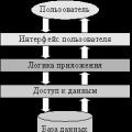 Architecture of a distributed control system based on a reconfigurable multi-pipeline computing environment L-Net "transparent" distributed file systems
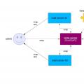 Email sending page Fill relay_recipients file with addresses from Active Directory
 Missing language bar in Windows - what to do?