Ethernet 4 cores. Twisted pair crimping scheme.
When creating any network, be it local or global, wires with appropriate connectors are used. The easiest option is a wire with RJ45. These are standard network wires, used to connect computers to switches, and enable a small network to be implemented.
Now we will learn how to crimp such cables, and consider all the pinout options for colors used when using 8-core wires.
Introduction
In fact, now even to create a simple local network on multiple computers, a wide variety of technologies can be used. It is not necessary to use standard 100 megabit Ethernet. It can be a wireless option, with using Wi-Fi router, and fiber-optic Internet access. But even in this case, if the rj45 wires are not used for installation, then they will definitely come in handy when setting up the equipment. At least for connecting the router to a personal computer, for initial configuration.
Another interesting point. Despite the possibility of using more modern technologies, while any computer is still equipped with a network card with an RJ45 interface.
Therefore, we need to know how to prepare and use a wire with an RJ45 connector.
To avoid confusion, let's make an agreement right away. A wire or cable with a RJ45 connector or connector, we will call the finished network wire, crimped with one of possible options... They are also often called twisted pair or UTP cable.
Interface, port or connector - the input for connecting such a cable. This can be a network card, a router interface, or a switch.
What do we need
To prepare the cable, we need the following things:
- Crimping tool
- Eight core UTP cable
- RJ-45 connectors
Cable crimp options
There are two main options.
- ... Used to connect personal computers to switches and routers. The most common cable option. The basic principle is the connection of two interfaces, in which different contacts are used to transmit and receive information.
- Crossover cable... In this way, we can connect two routers or switches together. Used for devices that use the same pins for transmit and receive on different ends
Thus, if we want to prepare a straight-through cable, at both ends, we must route the pins in the same way.
Shown here is the straight cable option.
In turn, the cross will have different connections of the conductors at the ends.
Additional wiring options
You need to know about one feature. In 100 Mbit networks, only 4 of the 8 cores of UTP wires are used to transfer information. The rest of them are reserved for gigabit networks. This allows additional options for crimping network cables.

Crossover cable.

We crimp the cable with our own hands
Take a crimp tool and two RJ45 connectors.

Measure the required length of the future cable, and cut it off, with a small margin.
Now at the end of the cable, make a small notch in the protective sheath, and cut it off. You need to free 2-3 centimeters of the veins. We unwind them.
After that, from each of the veins, we remove about 2 sentiments of the protective layer. To do this, cut it with scissors, a knife or a special tool, and tighten it. As a result, we should get 8 finished cleaned copper conductors in the cable.
Now we take the RJ-45 connector with the latch away from us and with the contacts facing up. Contact numbers in this position will be counted from left to right.
We leave it in this position, and select the required cable crimping option from those presented above. Now, based on the diagram, you should connect all the wires to the corresponding sockets on the connector.
At the same time, make sure that each core of a certain color corresponds to its place, based on the selected wiring diagram. Insert them all the way into the slots. When finished, place the pre-assembled RJ-45 jack into the crimping tool and secure it. This will make a network cable with an RJ-45 connector.

Do the same for the other end of the cable. After the RJ-45 crimp is complete, test the cable in action.
Video for the article:
Conclusion
When choosing network cable, consider its scope. Based on this, you need to choose a crimp option. It is considered good practice to mark the cable, indicating how it was crimped - straight or cross. This will help you avoid network creation problems.
In any case, check manually crimped wires with RJ-45 interfaces. For this, you can use special testers.
Needed for correct addressing between nodes.
Why look for information on other sites if everything is collected from us?
- - description, features, principle of operation
Cable layout for 10/100 Mbit / s networks.
Compound network devices performed by cable " twisted pair"with direct or cross type of wiring. Direct connection is used for switching a workstation or server with a hub (hub), switch (switch). Cross connection is used for switching devices of the same type, ie these are network connections:
- server server;
- workstation workstation;
- server workstation;
- hub hub;
- switch switch.
Sale of ready-made patchcords and computer cables- Buy a LAN cable.
Crimping network direct and crossover cable 10 / 100Mbit.
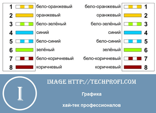
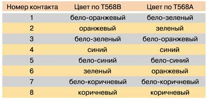
1. When connecting Computer-Hub / Switch (card-hub / switch), the following scheme is used:
1: White-orange
2: Orange
3: White-green
4: Blue
5: White-blue
6: Green
7: White-brown
8: Brown
According to this scheme, connectors are crimped on both sides of the "twisted pair".
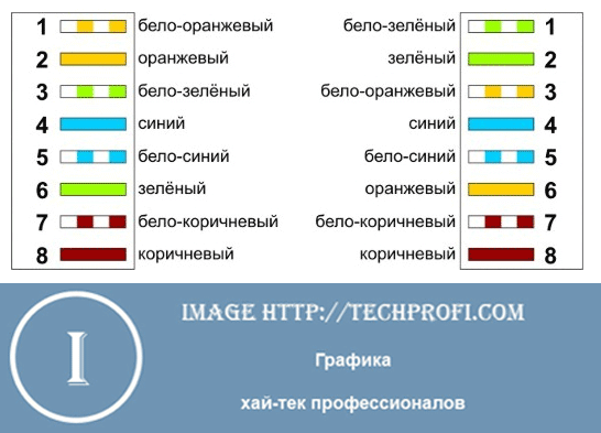
2. When connecting two crossover computers (card-card), the following twisted pair crimping scheme is used:
With this twisted pair crimping, the network will operate up to 100 Mbps..
| |Layout of pairs of wires in the RJ45 connector for crimping "twisted pair".
On 10/100 megabit connections:
The same pinout for both 10 and 100 megabit connections. It is widely used in the construction of entry-level / mid-level networks, including to connect to the Internet outlet.
The article contains color pinouts of rj-45 connectors for three main types of patchcords - straight through, crossover, and rollover.
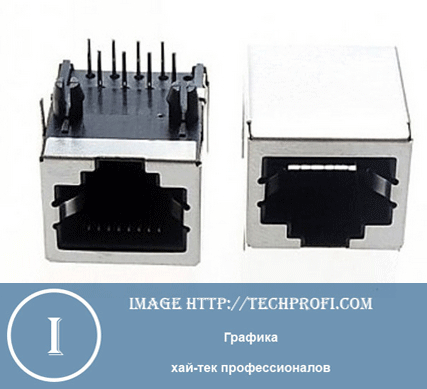
Type of connectors rj-45
Straight through cable
The most common type of cable used to connect network card computer and switch (switch).
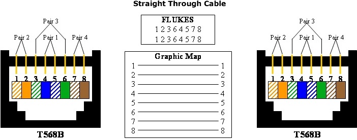
Color scheme for crimping the ends of a straight patch cord.
Note: for making a straight-through network cable, you can use only two pairs of orange and green (we use pin 1,2,3,6), however, the connection speed will only be up to 100 Mbps. For 1 Gbps, all four pairs must be used.
Crossover cable
Initially, it was used to connect the same type of equipment (for example, a switch to a switch, a computer to a computer, etc.). Recently, however, all modern network equipment supports the technology of automatic recognition and adjustment for different type crimping the cable (Auto MDI / MDI-X), i.e. if you connect two switches with a straight cable 99% that the devices will agree and will work.
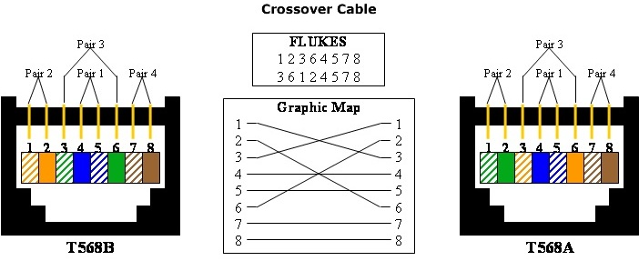
Color scheme for crimping the ends of the cross patch cord.
Note: All four pairs are always used to make a crossover cable.
Rollover cable
An inverted cable is often referred to as a console cable. it is mainly used to connect to the console ports of devices. It is the rarest type of cable, and if you are not a network administrator, you will most likely never need it.
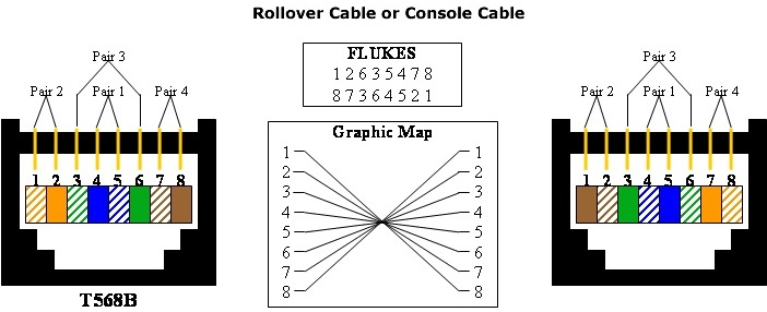
Color scheme for crimping the ends of an inverted patch cord.
That's all. We've covered three types of patchcords - straight through, crossover, and rollover.
A patch cord is an electrical cable, the ends of which are equipped with connectors. With it, you can easily connect one electrical device to another. In this article, we will show you how to make a patch cord yourself.
You will need the following tools:
- pliers for crimping contacts and RJ-45 connectors
- cable cutters
- tester
- coil of twisted pair cable
- RJ-45 connectors
Patch cord technology
Take the twisted-pair cable end from the coil. Measure a piece of the required length: the cable should freely reach from the computer to the switch, without blocking the passage. It is advisable to calculate the length of the cable so that later you can put it in its box or hide it behind the baseboard.
After choosing the appropriate length, cut the cable. Use the wire cutters (picture).
![]()
Carefully peel off the top protective layer (outer insulation) of the cut cable. If there is thread or insulating foil, cut it off. The insulation is removed at a length of approximately 30-40 mm from the end of the electrical cord.
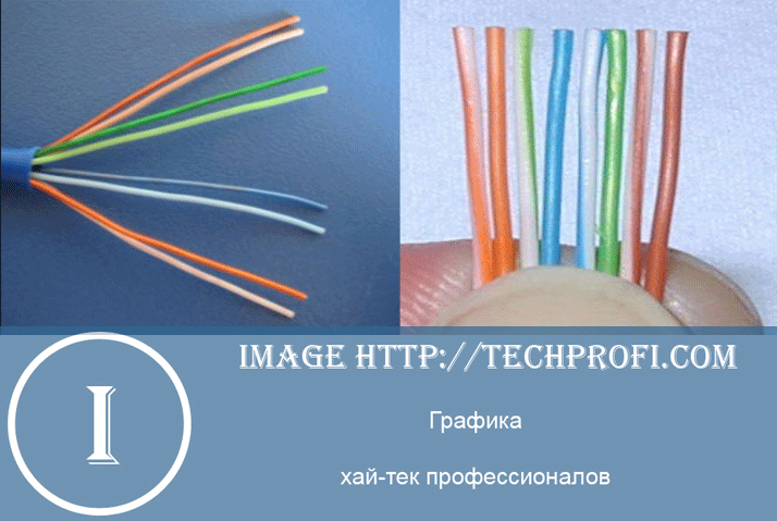
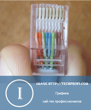
After you remove the top winding of the cable, you will see eight strands of wires that differ in color. They are twisted in pairs (figure).
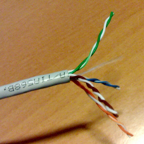
Spread out each wire. All wires must be absolutely flat, straight and clearly separated from each other.
The sequence is as follows (T568B), from left to right, as shown in the figure:
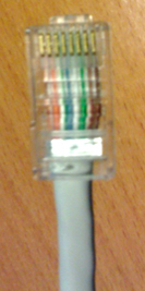
You should get the following look (picture):
![]()
Proceed to crimp the ends of the cable. You will need a crimping pliers.
Trim the end of your wires neatly:
Take the connector. Turn it with the tongue down, and the contacts up (picture):
While holding the pins, carefully insert the end of the cable all the way to the flange of the connector, so that each wire fits into its own path on the connector.
After making sure the pins are in the correct position, place the connector in the crimping pliers. They have a special connector, you will not confuse it.
While holding the cable, squeeze the pliers all the way - all contacts should "squeeze" well.
Release the pliers and remove the finished connector from them.
Repeat steps 3-15 for the other end of the cable.
When finished, you will receive your first patch cord. It should now be tested for 10BaseT category and operational readiness.
Pick up the tester and your patch cord.
Turn on the tester.
Insert the patch cord into the tester with both ends.
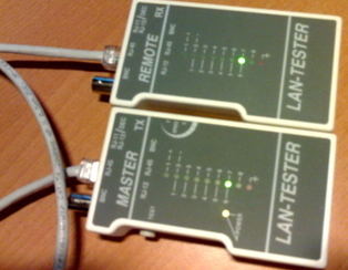
The tester will show whether your patch cord is working or not. If the indicators on both devices match, then the result is positive.
If the test was successful, then you can be congratulated! However, even if the test fails, do not despair: try cutting off the connectors from the patch cord with pliers and try again from the beginning.
 Wireless Charging Smartphones A5 Supports Wireless Charging
 Why do not MTS sms come to the phone?
 Why do you need a full reset on Android or how to return Android to factory settings