Low frequency transistor amplifier. Transistor amplifier: types, circuits, simple and complex. Amplifier with transformer output
Reading time ≈ 6 minutes
Amplifiers are probably one of the first devices that beginner radio amateurs begin to design. Collecting ULF transistors with their own hands using a ready-made circuit, many use microcircuits.
Transistor amplifiers, although they differ in a huge number, but every electronic engineer is constantly striving to do something new, more powerful, more complex, and interesting.
Moreover, if you need a high-quality, reliable amplifier, then you should look towards transistor models. After all, they are the cheapest, capable of producing clear sound, and any beginner can easily construct them.
Therefore, let's figure out how to make a homemade Class B bass amplifier.
Note! Yes, class amplifiersB can be good too. Many say that only tube devices can produce high-quality sound. This is partly true. But, take a look at their cost.

Moreover, assembling such a device at home is not an easy task. After all, you will have to look for the necessary radio tubes for a long time, and then buy them at a fairly high price. And the assembly and soldering process itself requires some experience.
Therefore, we will consider a circuit of a simple, and at the same time, high-quality low-frequency amplifier capable of delivering sound power of 50 watts.

An old but time-tested scheme from the 90s
The ULF circuit, which we will collect, was first published in the magazine "Radio" in 1991. It has been successfully collected by hundreds of thousands of radio amateurs. Moreover, not only for the improvement of skills, but also for use in their audio systems.
So, the famous Dorofeev's low-frequency amplifier:

The uniqueness and genius of this scheme lies in its simplicity. This ULF uses a minimum number of radioelements, and an extremely simple power source. But, the device is able to "take" a load of 4 Ohms, and provide an output power of 50 W, which is quite enough for a home or car speaker system.
Many electrical engineers have improved and refined this scheme. I. For convenience, we took the most modern version of it, replacing the old components with new ones, so that it would be easier for you to design the ULF:

Description of the low frequency amplifier circuit
In this "revised" Doroveevsky ULF, unique and most effective schematic solutions were used. For example, resistance R12. This resistor limits the collector current of the output transistor, thereby limiting the maximum power of the amplifier.
Important! Do not change the denominationR12 in order to increase the output power, since it is matched exactly to the components that are used in the circuit. This resistor protects the entire circuit from short circuits..

Output stage of transistors:

The same R12 "live":

Resistor R12 should have a power of 1 W, if this is not at hand, take half a watt. It has parameters that provide a harmonic distortion factor of up to 0.1% at a frequency of 1 kHz, and no more than 0.2% at 20 kHz. That is, you will not notice any changes by ear. Even when operating at maximum power.
The power supply unit of our amplifier must be bipolar, with output voltages within 15-25 V (+ - 1%):

To "raise" the sound power, you can increase the voltage. But, then it will be necessary to replace the transistors in the final stage of the circuit in parallel. You need to replace them with more powerful ones, and then recalculate several resistances.

Components R9 and R10 must be rated according to the applied voltage:

They, with the help of a zener diode, limit the passing current. In the same part of the circuit, a parametric stabilizer is assembled, which is needed to stabilize the voltage and current in front of the operational amplifier:


A few words about the TL071 microcircuit - the "heart" of our ULF. It is considered an excellent operational amplifier found in both hobbyists and professional audio equipment. If there is no suitable opamp, it can be replaced with TL081:

View "in reality" on the board:

Important! If you decide to use any other operational amplifiers in this circuit, carefully study their pinout, because the "legs" may have different meanings.
For convenience, the TL071 chip should be mounted on a plastic socket pre-soldered into the board. So it will be possible to quickly replace the component with another if necessary.
Good to know! For acquaintance, we will present you another circuit of this ULF, but without an amplifying microcircuit. The device consists exclusively of transistors, but it is extremely rarely assembled due to obsolescence and irrelevance.

To make it more convenient, we tried to make the printed circuit board as small as possible - for compactness and ease of installation in an audio system:


All jumpers on the board must be soldered immediately after etching.
Transistor blocks (input and output stages) must be mounted on a common radiator. Of course, they are carefully insulated from the heat sink.
In the diagram, they are here:

And here on the printed circuit board:

If ready-made ones are not available, radiators can be made of aluminum or copper plates:

The transistors of the output stage must have a power dissipation of at least 55 W, and even better - 70 or as much as 100 W. But, this parameter depends on the supply voltage supplied to the board.


It is clear from the circuit that 2 complementary transistors are used at the input and output stages. It is important for us to select them according to the amplifying factor. To determine this parameter, you can take any multimeter with a transistor test function:


If you do not have such a device, then you will have to borrow a transistor tester from some masters:


Zener diodes should be selected according to their power per half watt. Their stabilization voltage should be 15-20 V:


Power Supply. If you plan to mount a transformer power supply unit on your ULF, then select filter capacitors with a capacity of at least 5000 uF. Here the more the better.


The bass amplifier we have assembled belongs to the B-class. It works stably, providing almost crystal clear sound. But, BN is best selected so that it could not work at full capacity. The best option is a transformer with an overall power of at least 80 W.
That's all. We figured out how to assemble an ULF on transistors with our own hands using a simple circuit, and how it can be improved in the future. All the components of the device will be found, and if they are not there, it is worth disassembling a couple of old tape recorders or ordering radio parts on the Internet (they cost almost a penny).
The editors of the site "Two Schemes" present a simple but high-quality low-frequency amplifier based on MOSFET transistors. Its circuit should be well known to radio amateurs and audiophiles, since it is already 20 years old. The circuit is the development of the famous Anthony Holton, therefore it is sometimes called that - ULF Holton. The sound amplification system has low harmonic distortion, not exceeding 0.1%, with a power per load of about 100 watts.
This amplifier is an alternative for the popular TDA series amplifiers and similar pop amplifiers, because at a slightly higher cost, you can get an amplifier with clearly better characteristics.
The big advantage of the system is its simple design and an output stage consisting of 2 inexpensive MOSFETs. The amplifier can work with speakers with impedance of both 4 and 8 ohms. The only adjustment that needs to be done during startup is to set the quiescent current value of the output transistors.
Schematic diagram of UMZCH Holton
 Holton MOSFET Amplifier - Circuit
 The circuit is a classic two-stage amplifier, it consists of a differential input amplifier and a balanced power amplifier, in which one pair of power transistors operates. The system diagram is presented above.
Printed circuit board


 ULF printed circuit board - finished view
 Here is an archive with PDF files of the PCB -.
The principle of the amplifier
Transistors T4 (BC546) and T5 (BC546) operate in a differential amplifier configuration and are designed to be powered from a current source built on the basis of transistors T7 (BC546), T10 (BC546) and resistors R18 (22 kΩ), R20 (680 Ohm) and R12 (22 rooms). The input signal is fed to two filters: a low-pass filter, built of elements R6 (470 ohms) and C6 (1 nF) - it limits the high-frequency components of the signal and a band-pass filter consisting of C5 (1 μF), R6 and R10 (47 kOhm), limiting signal components at infra-low frequencies.
The differential amplifier is loaded with resistors R2 (4.7 kΩ) and R3 (4.7 kΩ). Transistors T1 (MJE350) and T2 (MJE350) are another amplification stage, and its load is transistors T8 (MJE340), T9 (MJE340) and T6 (BD139).
Capacitors C3 (33pF) and C4 (33pF) counteract amplifier excitation. Capacitor C8 (10 nF) in parallel with R13 (10 kΩ / 1 V) improves the ULF transient response, which is important for fast-rising input signals.
Transistor T6, together with elements R9 (4.7 ohms), R15 (680 ohms), R16 (82 ohms) and PR1 (5 ohms), allows you to set the correct polarity of the amplifier output stages at rest. Using a potentiometer, it is necessary to set the quiescent current of the output transistors within 90-110 mA, which corresponds to a voltage drop across R8 (0.22 Ohm / 5 W) and R17 (0.22 Ohm / 5 W) within 20-25 mV. The total quiescent current consumption of the amplifier should be in the region of 130 mA.
The output elements of the amplifier are MOS transistors T3 (IRFP240) and T11 (IRFP9240). These transistors are installed as a voltage follower with a large maximum output current, so the first 2 stages must swing a sufficiently large amplitude for the output signal.
Resistors R8 and R17 were mainly used to quickly measure the quiescent current of power amplifier transistors without interfering with the circuit. They can also come in handy in the case of expanding the system to one more pair of power transistors, due to the differences in the resistance of the open channels of the transistors.
Resistors R5 (470 Ohm) and R19 (470 Ohm) limit the charging rate of the capacitance of the pass-through transistors, and, therefore, limit the frequency range of the amplifier. Diodes D1-D2 (BZX85-C12V) protect power transistors. With them, the voltage at startup relative to the power supplies for the transistors should not exceed 12 V.
The amplifier board provides places for the power filter capacitors C2 (4700 μF / 50 V) and C13 (4700 μF / 50 V).
 Homemade transistor ULF on MOSFET
 The control is powered through an additional RC filter built on the elements R1 (100 Ohm / 1 V), C1 (220 μF / 50 V) and R23 (100 Ohm / 1 V) and C12 (220 μF / 50 V).
Power supply for UMZCH
The amplifier circuit provides power that reaches real 100 watts (effective sinusoidal), with an input voltage in the region of 600 mV and a load resistance of 4 ohms.
 Holton amplifier on board with details
 The recommended transformer is a 200 W toroid with a voltage of 2x24 V. After rectification and smoothing, a two-polar power supply of the power amplifiers should be obtained in the region of +/- 33 Volts. The design presented here is a very good performance mono amplifier module built on MOSFETs that can be used as a stand-alone unit or as a set.
Readers! Remember the nickname of this author and never repeat his schemes.
Moderators! Before you ban me for insults, think that you have "let an ordinary gopnik near the microphone", who should not even be allowed close to radio equipment and, moreover, to teaching beginners.
Firstly, with such a switching scheme, a large direct current will flow through the transistor and speaker, even if the variable resistor is in the right position, that is, music will be heard. And with a large current, the speaker is damaged, that is, sooner or later, it will burn out.
Secondly, in this circuit there must be a current limiter, that is, a constant resistor, at least 1 KOhm, connected in series with a variable. Any homemade product will turn the variable resistor regulator all the way, it will have zero resistance and a large current will go to the base of the transistor. As a result, the transistor or speaker will burn out.
A variable capacitor at the input is needed to protect the sound source (the author should explain this, for immediately there was a reader who removed it just like that, considering himself smarter than the author). Without it, only those players in which such protection is already installed on the output will work normally. And if it is not there, then the output of the player may be damaged, especially, as I said above, if you unscrew the variable resistor "to zero". In this case, the output of an expensive laptop will be supplied with voltage from the power source of this penny trinket and it may burn out. Self-made, very fond of removing protective resistors and capacitors, because "it works the same!" As a result, the circuit can work with one sound source, but not with another, and even an expensive phone or laptop can be damaged.
The variable resistor, in this circuit, should only be a trimmer, that is, it should be adjusted once and closed in the case, and not brought out with a convenient handle. This is not a volume control, but a distortion control, that is, it selects the operating mode of the transistor so that there is minimal distortion and that smoke does not come from the speaker. Therefore, in no case should it be accessible from the outside. You can NOT adjust the volume by changing the mode. For this you need to "kill". If you really want to control the volume, it's easier to turn on another variable resistor in series with the capacitor, and now it can be brought out to the amplifier case.
In general, for the simplest circuits - and in order to work immediately and in order not to damage anything, you need to buy a TDA-type microcircuit (for example, TDA7052, TDA7056 ... there are many examples on the Internet), and the author took a random transistor that was lying around in his desk. As a result, gullible amateurs will look for just such a transistor, although its gain is only 15, and the permissible current is as much as 8 amperes (it will burn any speaker without even noticing it).
Single transistor amplifier- here is the design of a simple ULF on one transistor. It was with such schemes that many radio amateurs began their journey. Once we have assembled a simple amplifier, we always strive to make a more powerful and high-quality device. And so everything goes on increasing, there is always a desire to make an impeccable power amplifier.
The simplest amplifier circuit shown below is based on one bipolar transistor and six electronic components, including a speaker. This design of the device for amplifying the sound of low frequency, was created just for the novice radio amateurs. Its main purpose is to make it clear the simple principle of operation of the amplifier, therefore it is assembled using a minimum number of electronic elements.
This amplifier naturally has a small power, for a start it is large and is not needed. However, if you install a more powerful transistor and raise the supply voltage a little, then you can get about 0.5 watts at the output. And this is already considered a pretty decent power for an amplifier with such a design. In the diagram, for clarity, a bipolar transistor with n-p-n conductivity is used, but you can use any and with any conductivity.
To get 0.5 W at the output, it is best to use powerful bipolar transistors such as KT819 or their foreign counterparts, for example 2N6288, 2N5490. You can also use silicon transistors such as KT805, their foreign counterpart - BD148, BD149. The capacitor in the output path circuit can be set to 0.1mF, although its nominal value does not play a big role. Nevertheless, it forms the sensitivity of the device relative to the frequency of the audio signal.
If you put a capacitor with a large capacity, then the output will be mainly low frequencies, and high frequencies will be cut off. Conversely, if the capacitance is small, then low frequencies will be cut, and high frequencies will be skipped. Therefore, this output capacitor is selected and installed based on your preference for the audio range. The supply voltage for the circuit must be selected in the range from 3v to 12v.
I would also like to clarify - this power amplifier is presented to you for demonstration purposes only, to show the principle of operation of such a device. The sound of this device will of course be at a low level and cannot be compared with high-quality devices. When you increase the playback volume, distortion in the form of wheezing will occur in the speaker.
Scheme No. 1
Amplifier class selection ... We will immediately warn the radio amateur - we will not make a class A amplifier using transistors. The reason is simple - as mentioned in the introduction, the transistor amplifies not only the useful signal, but also the bias applied to it. Simply put, it amplifies the direct current. This current, together with the useful signal, will flow through the acoustic system (AC), and the speakers, unfortunately, are able to reproduce this constant current. They do this in the most obvious way - by pushing or pulling the diffuser from its normal position into an unnatural one.
Try to press the speaker cone with your finger - and you will see what a nightmare the sound will turn into. Direct current in its action successfully replaces your fingers, so it is absolutely contraindicated in a dynamic head. It is possible to separate the direct current from the alternating signal only by two means - a transformer or a capacitor - and both options, as they say, are one worse than the other.
Schematic diagram
The diagram of the first amplifier that we will assemble is shown in Fig. 11.18.
This is a feedback amplifier, the output stage of which operates in the B mode. The only advantage of this circuit is its simplicity, as well as the uniformity of the output transistors (no special complementary pairs are required). Nevertheless, it is widely used in low power amplifiers. Another plus of the scheme is that it does not require any configuration, and if the parts are intact, it will work right away, and this is very important for us now.
Let's consider how this scheme works. The amplified signal is fed to the base of the transistor VT1. The signal amplified by this transistor from the resistor R4 is fed to the base of the composite transistor VT2, VT4, and from it to the resistor R5.
Transistor VT3 is turned on in emitter follower mode. It amplifies the positive half-waves of the signal across the resistor R5 and feeds them through the capacitor C4 to the AC.
The negative half-waves are amplified by the composite transistor VT2, VT4. In this case, the voltage drop across the diode VD1 closes the transistor VT3. The signal from the amplifier output is fed to the feedback loop divider R3, R6, and from it to the emitter of the input transistor VT1. Thus, the transistor VT1 we have and plays the role of a comparison device in the feedback circuit.
It amplifies the direct current with a gain equal to unity (because the resistance of capacitor C to direct current is theoretically infinite), and the useful signal with a factor equal to the ratio R6 / R3.
As you can see, the value of the capacitive resistance of the capacitor is not taken into account in this formula. The frequency, starting from which the capacitor can be neglected in the calculations, is called the cutoff frequency of the RC-chain. This frequency can be calculated by the formula
F = 1 / (R × C).
For our example, it will be about 18 Hz, i.e., the amplifier will amplify lower frequencies worse than it could.
Pay ... The amplifier is assembled on a board made of one-sided fiberglass with a thickness of 1.5 mm and dimensions of 45 × 32.5 mm. The mirrored PCB layout and layout are available for download. You can download a video about the amplifier in MOV format for viewing. I want to warn the radio amateur right away - the sound reproduced by the amplifier was recorded in the video using the microphone built into the camera, so talking about the sound quality, unfortunately, will not be entirely appropriate! The external view of the amplifier is shown in Fig. 11.19.
Element base ... In the manufacture of the amplifier, transistors VT3, VT4 can be replaced with any transistors designed for a voltage of at least the amplifier supply voltage, and with an allowable current of at least 2 A. The diode VD1 must be calculated for the same current.
The rest of the transistors - any with an allowable voltage of at least the supply voltage, and an allowable current of at least 100 mA. Resistors - any with a permissible dissipated power of at least 0.125 W, capacitors - electrolytic, with a capacity not less than that indicated in the diagram, and an operating voltage less than the supply voltage of the amplifier.
Amplifier radiators ... Before trying to make our second design, let’s, dear radio amateur, dwell on the radiators for the amplifier and give here a very simplified method for calculating them.
First, we calculate the maximum power of the amplifier using the formula:
P = (U × U) / (8 × R), W,
where U- amplifier supply voltage, V; R- speaker resistance (usually it is 4 or 8 ohms, although there are exceptions).
Secondly, we calculate the power dissipated on the collectors of transistors using the formula:
P races = 0.25 × P, W.
Third, we calculate the radiator area required to remove the corresponding amount of heat:
S = 20 × P races, cm 2
Fourthly, we select or manufacture a radiator, the surface area of which will not be less than the calculated one.
The indicated calculation is very approximate, but for amateur radio practice it is usually sufficient. For our amplifier with a supply voltage of 12 V and an AC resistance of 8 ohms, the "correct" heatsink would be an aluminum plate 2 × 3 cm in size and at least 5 mm thick for each transistor. Note that a thinner plate does not transfer heat well from the transistor to the edges of the plate. I would like to warn you right away - the radiators in all other amplifiers must also be "normal" in size. Which ones - count for yourself!
Sound quality ... Once you assemble the circuit, you will find that the sound of the amplifier is not entirely clear.
The reason for this is the "pure" class B mode in the output stage, the characteristic distortions of which even the feedback is not able to fully compensate. For the sake of experiment, try replacing the VT1 transistor in the circuit with KT3102EM, and the VT2 transistor with KT3107L. These transistors have a significantly higher gain than KT315B and KT361B. And you will find that the sound of the amplifier has improved significantly, although some distortion will still be noticeable.
The reason for this is also obvious - a higher gain of the amplifier as a whole provides more accurate feedback, and a greater compensating effect.
Continue read
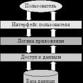 Architecture of a distributed control system based on a reconfigurable multi-pipeline computing environment L-Net "transparent" distributed file systems
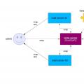 Email sending page Fill relay_recipients file with addresses from Active Directory
 Missing language bar in Windows - what to do?