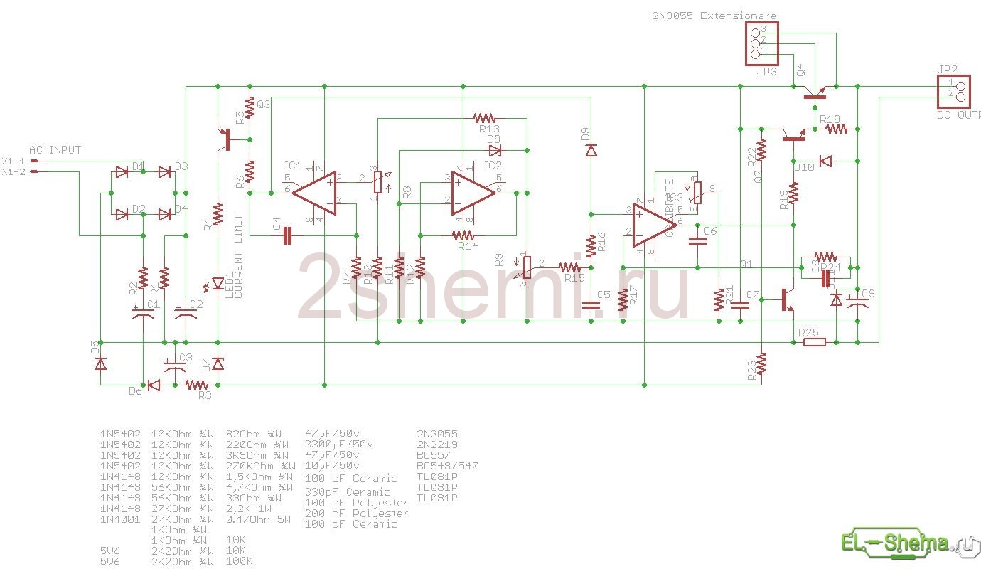
Power supply circuit with current and voltage adjustments
I took this scheme on the Internet, many years ago. The reason why I decided to post it is that there are errors in the original, which I fixed. Therefore, you can safely take the circuit and make this power supply. He has been working for me for four years.
This power supply is built on a common radio element base and does not contain scarce parts. A feature of the unit is that the adjustable DA4 microcircuit does not require a two-pole power supply. On the DA1 microcircuit, a smooth adjustment of the output current in the range of 0 ... 3A (according to the diagram) is introduced. This limit can be extended to 5A by recalculating the resistor R4. In the author's version, the resistor R7 is replaced with a trimmer, since smooth current regulation was not required. The current limitation with the set ratings of the parts occurs at a current of 3.2A and the output voltage drops to 0. The current limitation is selected by the resistor R7. During current limitation, the HL1 LED turns on, signaling a short circuit in the power supply load or an excess of the selected current value by resistor R7. If the response threshold of 1.5A is selected by the resistor R7, then when this threshold is exceeded, the output of the microcircuit will appear low voltage(-1.4V) and 127mV will be established on the basis of the VT2 transistor. The voltage at the output of the power supply unit becomes equal to »1mkV, which is normal for most radio amateur tasks, and the voltage indication unit will be at 00.0 volts. The HL1 LED will be on. During normal operation of the overcurrent node based on the DA1 microcircuit, there will be a voltage of 5.5V and the HL1 diode will not light up.
The characteristics of the power supply are as follows:
The output voltage is adjustable from 0 to 30 V.
Output current 4A.
The work of the DA4 microcircuit has no peculiarities and it works in the mode of unipolar power supply. 9V is supplied to leg 7, leg 4 is connected to a common bus. Unlike most microcircuits of the 140UD series ... it is very difficult to achieve a zero level at the output of the power supply unit with this inclusion. Experimentally, the choice was made on the KR140UD17A microcircuit. With such a circuit solution, it was possible to obtain a voltage of 156 μV at the output of the power supply, which will be displayed as 00.0V on the indicator.
Capacitor C5 prevents excitation of the power supply.
With serviceable parts and error-free installation, the power supply starts working immediately. Resistor R12 is installed top level output voltage, within 30.03V. The VD5 zener diode is used to stabilize the voltage across the regulating resistor R16 and, if the power supply works without interruptions, the zener diode can be abandoned. If the resistor R7 is used as a trimmer, then they set the operating threshold when the maximum current is exceeded.
The VT1 transistor is installed on the radiator. The radiator area is calculated by the formula: S = 10In * (Uin. - Uout.), Where S is the radiator surface area (cm 2); In - maximum current consumed by the load; Uin. - input voltage (V); Uout. - output voltage (V).
The power supply circuit is shown in Fig. 1, the printed circuit board in Figures 2 and 3.
What is highlighted in red are the errors that I fixed. If this is not done, the scheme does not work.
Resistors R7 and R12 are multiturn SP5-2. Instead of a diode assembly RS602, you can use a diode assembly RS407, RS603, depending on the current consumption, or diodes 242 with any letter index, but they must be placed separately from the printed circuit board. The input voltage on the capacitor C1 can vary within 35 ... 40V without changing the ratings of the parts. Transformer T1 must be rated for a power of at least 100 W, winding current II is at least 5 A at a voltage of 35 ... 40 V. Winding current III is at least 1 A. Winding III SHOULD (otherwise the circuit will not work, this is one of the errors) be with a tap from the middle, which is connected to the common bus of the power supply. A contact pad is provided on the printed circuit board for this purpose. The size of the printed circuit board of the power supply is 110 x 75 mm. The KT825 transistor is composite and it costs a lot, so it can be replaced with transistors, as shown in Figure 4.
Transistors can be with letter indices B - G, connected according to the Darlington circuit.
Resistor R4 is a piece of nichrome wire with a diameter of 1 mm and a length of about 7 cm (selected experimentally). Microcircuits DA2, DA3 and DA5 can be replaced by domestic counterparts K142EN8A, KR1168EN5 and K142EN5A. If the digital display panel will not be used, then KR1157EN902 can be used instead of the DA2 microcircuit, and the DA5 microcircuit can be excluded. Resistor R16 variable with the dependence of group A. variable resistor PPB-3A with a nominal value of 2.2K - 5%.
If you do not impose great demands on the protection node, and it will only be required to protect the power supply from overcurrent and short-circuit, then such a node can be used according to the diagram in Fig. 6, and the printed circuit board can be slightly reworked.
The protection unit is assembled on transistors VT1 and VT2 of different structures, resistors R1 - R3 and capacitor C1. Short circuit current 16mA. Resistor R1 regulates the threshold of the protective block. During normal operation of the unit at the emitter of the transistor VT2, the voltage is about 7 V and does not affect the operation of the power supply. When the protection is triggered, the voltage at the emitter of the transistor VT2 drops to 1.2 V and is fed through the diode VD4 to the base of the transistor VT2 of the power supply. The voltage at the output of the power supply drops to 0 V. and the HL1 LED signals the protection operation. During normal operation of the power supply and the protection unit, the LED is on, when the protection is triggered, it goes out. When using the protection unit in Fig. 6, the DA3 microcircuit and capacitors C3, C5 can be excluded from the circuit.
The digital panel serves for visual control of the voltage and current of the power supply. It can be used separately from the power supply with other designs, performing the above tasks.
I took the voltmeter and ammeter from here.
Here are some photos of my power supply, which show that I also attached a fan for cooling, the power of which I took from the third winding of the transformer, having previously wound it with this calculation.
(click on the images to enlarge)
Alexander, thank you for the work done!
SPECIFICATIONS
| DC Power Supply Specifications | |
| Output voltage |
0 - 30V (adjustable) |
| Output current |
0 - 10 A (adjustable) |
| output power |
300 watts |
| Input voltage |
220V / 50Hz (default) |
| Accuracy of setting of indications | voltage: 0.1 V; current: 0.1 A (± 1%) |
| Voltage stability | ≤ 0.05% + 1 mV |
| Current stability | ≤ 0.1% + 10mA |
| Influence of load | CV ≤ 0.1% + 1mV CC ≤ 0.1 + 10 mA |
| Ripple and noise | CV ≤ 10 mV (RMS) CC ≤ 20 mA (RMS) |
| Cooling | air cooling |
| Protection: | |
| OVP (Output Over Voltage Protection) | there is |
| OCP (overcurrent protection for any of the outputs) | there is |
| OTP (overheating protection) | there is |
| General characteristics | |
| Colour | White |
| Display | 3LED display |
| Screen backlight | Yes |
| Storage temperature range | -20 ° С - + 80 ° С |
| Operating temperature range | 0 ° С - + 40 ° С |
| Dimensions (edit) | 260mm x 125mm x 155mm |
| Equipment | DC power supply MAISHENG MS3010D - 1 piece |
| power cable - 1 piece power supply wires (banana + crocodile) - 1 piece instruction manual - 1 piece |
|
Necessary equipment in the laboratory of the radio amateur
Any electronic device designed with active components, from simple radios to personal computers need power supplies. To ensure the normal functioning of a certain load, it is necessary to select a secondary power supply source (IVEP) that meets the requirements that dictate the load of modern equipment.
MAISHENG specializes in the development of laboratory power supplies. These are stabilized high-precision devices of increased power with the ability to adjust constant voltage and current. MAISHENG MS3010D is a popular pulse type MS series PSU, suitable for most amateur radio applications.
A switching power supply is an inverter system in which the incoming current is first rectified and then converted into square-wave pulses. Unlike a linear one, a switching power supply does not have a powerful, bulky transformer. The rectified mains voltage is fed to the input of the inverter, converted into AC voltage high frequency, is rectified and transmitted to the input of the linear stabilizer. Due to this, high efficiency is achieved, the power supply unit looks compact and weighs little.
The presence of a voltage stabilization circuit allows the power supply to differ in less fluctuation of this indicator, relative to unstabilized options. Maintaining a stable output voltage is achieved by a feedback compensation principle.
The MS3010D industrial DC power supply has the ability to vary the voltage and current from zero to 30 V and 10 A, respectively. It is a quality tool for laboratory and adjustment work. The single-channel power supply unit has a flexible interface with encoders for quick setting of parameters with an accuracy of 0.1 V / 0.1 A. For convenience, it is equipped with a LED display with digital indication, has a low level of ripple and noise. It is quite lightweight and mobile, protected from overloads and overheating. The device is temperature stable and does not require additional cooling.
Compatibility:Video reviews:
We assemble an adjustable power supply unit 0 ... 30V / 5A.
Decided to assemble a power supply unit, and do not know which circuit to stop on? Indeed, on the Internet you can find many schematic diagrams of these devices. Well, in this article, we will consider a power supply circuit implemented on a domestic element base, these components from which the circuit is assembled are quite widespread and not at all in short supply, and this is a big plus of this option. The second plus of this circuit is that the output voltage of the power supply is regulated in a wide range, and lies in the range from 0 to 30 Volts, while the output current can reach 5 Amperes. And one more important point, this circuit has overload and short circuit protection in the load. The schematic diagram is shown in the figure below:
Consider what nodes the circuit consists of:
A step-down transformer. Its power should be about 150 watts. For example, you can rewind the secondary windings of the TC-160 transformer, or use iron similar to it. When modifying the TC-160, the primary winding remains unchanged. The second winding is designed for a voltage of 28 ... 30 Volts, and a current of at least 5 ... 6 Amperes. The third winding should provide 5 ... 6 Volts with a current of at least 1 Ampere.
Rectifier assembly. It consists of a diode bridge VD1 ... VD4, and a smoothing capacitance C1. The printed circuit board provides for the use of an imported RS603 (RS602) diode assembly for a current of 10 Amperes, but it is possible to assemble a bridge from individual domestic diodes, for example, D242, although the dimensions of the device will naturally increase.
The KTs407 diode bridge and two integral stabilizers 7805 and 7905 form a power supply unit for the regulation and protection unit. Instead of KTs407, you can put KTs402 or KTs405.
Protection is assembled on the KU101E thyristor, the VD9 LED indicates its state, in case of overload and short circuit, it lights up. A resistor R4 is installed as a current sensor, in the circuit it is designed for a current of 3 Amperes, for 5 Amperes it must be recalculated.
The regulating element is a powerful silicon transistor VT1 (KT827A). It must be installed on a radiator with a cooling area of at least 1500 sq. see.If there are difficulties with the acquisition of KT827A, then instead of it you can put a pair of transistors connected according to the following scheme:

Resistor R7 regulates the minimum voltage of the PSU output. The potentiometer knob R13 is brought out to the front panel of the power supply and is a regulator of the output voltage. Rotating R14 adjusts the upper limit of the output voltage. R7 and R14 - multi-turn type SP5.
The figures below show a variant of the printed circuit board of the power supply:


The printed circuit board has dimensions of 110x75 mm.
Setting up the power supply:
The whole setting of the power supply boils down to setting the necessary limits for adjusting the output voltage, as well as the magnitude of the current at which the protection will operate. As already mentioned above, the protection current depends on the value of the resistor R4.
To determine the range of regulation of the output voltage, do the following:
Set potentiometers R7 and R13 to the middle position.
Measuring with a voltmeter Uout. Use resistor R14 to set the value to 15 Volts.
Turn R13 to minimum and use R7 to set the output to zero volts.
Now R13 is at maximum and with R14 set the output to 30 Volts. If necessary, instead of R14 (by measuring its readings), you can solder a constant resistance.
This completes the setup, if everything is assembled without blunders and errors, the power supply will work like a clock. This concludes the article, happy repetition.
This regulated power supply is made according to a very common scheme (which means it has been successfully repeated hundreds of times already) on imported radioelements. The output voltage varies smoothly within 0-30 V, the load current can reach 5 amperes, but since the transformer was not too powerful, it was possible to remove only 2.5 A.
Power supply circuit with current and voltage adjustments
 Schematic diagram
 | R1 = 2.2 KOhm 1W |
| R2 = 82 Ohm 1 / 4W |
| R3 = 220 Ohm 1 / 4W |
| R4 = 4.7 KOhm 1 / 4W |
| R5, R6, R13, R20, R21 = 10 KOhm 1 / 4W |
| R7 = 0.47 Ohm 5W |
| R8, R11 = 27 KOhm 1 / 4W |
| R9, R19 = 2.2 KOhm 1 / 4W |
| R10 = 270 KOhm 1 / 4W |
| R12, R18 = 56KOhm 1 / 4W |
| R14 = 1.5 KOhm 1 / 4W |
| R15, R16 = 1 KOhm 1 / 4W |
| R17 = 33 Ohm 1 / 4W |
| R22 = 3.9 KOhm 1 / 4W |
| RV1 = 100K trimmer |
| P1, P2 = 10KOhm linear pontesiometer |
| C1 = 3300 uF / 50V electrolytic |
| C2, C3 = 47uF / 50V electrolytic |
| C4 = 100nF polyester |
| C5 = 200nF polyester |
| C6 = 100pF ceramic |
| C7 = 10uF / 50V electrolytic |
| C8 = 330pF ceramic |
| C9 = 100pF ceramic |
| D1, D2, D3, D4 = 1N5402,3,4 diode 2A - RAX GI837U |
| D5, D6 = 1N4148 |
| D7, D8 = 5.6V Zener |
| D9, D10 = 1N4148 |
| D11 = 1N4001 diode 1A |
| Q1 = BC548, NPN transistor or BC547 |
| Q2 = 2N2219 NPN transistor |
| Q3 = BC557, PNP transistor or BC327 |
| Q4 = 2N3055 NPN power transistor |
| U1, U2, U3 = TL081, operational amplifier |
| D12 = LED diode |
Here's another version of this scheme:
Parts used
A TS70 / 5 transformer (26 V - 2.28 A and 5.8 V - 1 A) was used here. A total of 32 volts secondary voltage. In this version, the uA741 opamp is used instead of the TL081, since they were available. Transistors are also not critical - if only they fit in current and voltage, well, and naturally in structure.
 PCB with details
 The LED signals the transition to CT mode (stable current). This is not a short circuit or an overload, but current stabilization is a useful function of the power supply. This can be used, for example, to charge batteries - in idle mode, the final voltage value is set, then we connect the wires and set the current limit. In the first phase of charging, the power supply unit operates in CT mode (the LED is on) - the charging current is as set, and the voltage slowly rises. When, as the battery is charging, the voltage reaches the set threshold, the power supply goes into voltage stabilization (CH) mode: the LED goes out, the current begins to decrease, and the voltage remains at the set level.
The limiting value of the supply voltage across the filter capacitor is 36 V. Pay attention to its voltage - otherwise it will not stand up and blast!
Sometimes it makes sense to use two potentiometers each to regulate current and voltage according to the principle of coarse and fine adjustment.
 View of the inside of the case on the indicators
 The wires inside should be tied into bundles with thin cable ties.
 Diode and transistor on the heatsink
 Homemade power supply case
For the power supply unit, the case of the Z17W model is used. The printed circuit board is located at the bottom, screwed to the bottom with 3 mm screws. Under the body are attached black rubber legs from some kind of device, instead of the hard plastic ones that were included. This is important, otherwise when you press the buttons and turn the knobs, the power supply will "ride" on the table.
 Regulated power supply: self-made design
 The front panel inscriptions are made in graphic editor, then printing on self-adhesive chalk paper. Here's a homemade product, and if you don't have enough of this power -.
Power supply specifications: The output voltage is adjustable from 0 to 30 volts. Output current 5 amps. The voltage drop at a current from 1 to 6 amperes is negligible and is not reflected in the output indicators. This power supply unit contains three main nodes: an internal network power supply unit VD1-VD4, C1-C7, DA1, DA2, an overload and short-circuit protection unit on VS1, R1-R4, VD3 and the main unit - an adjustable voltage stabilizer VT2-VT7, VD4-VD5, R4-R14, C8. Diode HL1 indicates overcurrent or short circuit in the load.The main unit is an adjustable compensation-type voltage regulator. It contains an input differential stage on transistors VT5, VT7, two amplification stages on transistors VT3 and VT2, and a regulating transistor VT 1. Elements VT4, VT6, VD4, VD5, R5 - R8, R10 form current stabilizers. Capacitor C8 prevents self-excitation of the unit. The output voltage is regulated by resistor R13. The upper voltage limit is a trimming resistor R14. Construction and details. The power of the transformer T1 must be at least 100 - 160 watts, the current of winding II - at least 4 - 6 amperes. Winding current III - within 1 ... 2 amperes. Transistor VT1 should be installed on finned aluminum radiators with an area of more than 1450 sq. Cm. Resistor R4 is selected experimentally, according to the protection operation current.
Resistors R 7 and R 14 are multiturn SP5-2. Resistor - R13 any variable. Microcircuits DA1 and DA2 can be replaced with similar domestic KR142EN5A and KR1162EN5A. Their power allows a stabilized voltage of ± 5 volts to power external loads with a current consumption of up to 1 ampere. This load is a digital panel, which is used for digital indication of voltage and current in power supplies. If you do not use a digital panel, then DA1 and DA2 microcircuits can be replaced with 78L05 and 79L05 microcircuits. Diodes VD3 - VD5 can be replaced with diodes KD522B. The digital panel consists of an input voltage and current divider, a KR572PV2A microcircuit and an indication of four seven-segment LED indicators... Resistor R4 of the digital panel consists of two pieces of constantan wire = 1 mm and a length of 50 mm. The difference in the resistor value must exceed 15 - 20%. Resistors R2 and R6 of the SP5-2 and SP5-16VA brands. Switch of modes of indication of voltage and current type P2K. The KR572PV2A microcircuit is a 3.5 decimal place converter operating on the principle of sequential counting with double integration, with automatic zero correction and determination of the polarity of the input signal. Imported seven-segment LED indicators KINGBRIGT DA56 - 11 SRWA with a common anode were used for indication. It is advisable to use film capacitors C2 - C4 of the K73-17 type. Instead of imported seven-segment LEDs, domestic ones with a common anode of the ALS324B type can be used.
All radio components of the device:
VD1 - VD4 - RS600
VD5 - VD8 - KS407A
VD9 - AL307B
VD10 - KD102A
VD11 - 1N4148
VD12 - 1N4148
C1 - 10000 μF x 50 volts
C2 - 100 μF
C3 - 100 uF
C4 - 10 μF
C5 - 10 μF
C6 - 10 n
C7 - 10 n
C8 - 33 n
R1 - 330 Ohm
R2 - 3 kOhm
R3 - 33 Ohm
R4 - 2.4 kOhm
R5 - 150 Ohm
R6 - 2.2 kOhm
R7 - 10 kOhm
R8 - 330 kOhm
R9 - 6.8 kOhm
R10 - 1 kOhm
R11 - 5.1 kOhm
R12 - 5.1 kOhm
R13 - 10 kOhm
R14 - 2.2 kOhm
VT1 - KT827A
VT2 - KT815G
VT3 - KT3107A
VT4 - KT3102A
VT5 - KT315D
VT6 - KT315D
VT7 - KT315D
After turning on the power and error-free installation, if the parts are intact, the indication segments HG1-HG3 should light up. According to the voltmeter, the resistor R2 at pin 36 of the KR572PV2 microcircuit sets a voltage of 1 volt. Connect the power supply to legs (a) and (b). At the output of the power supply, a voltage of 5 ... 15 volts is set and a resistor R 10 (roughly) is selected, replacing it, for a while, with a variable.

With the resistor R8, a more accurate voltage reading is set. After that, a variable resistor with a power of 10 ... 30 watts is connected to the output of the power supply, the current is set to 1 ampere by the ammeter and the value on the indicator is set by the resistor R 6. The reading should be 1.00. At a current of 500 mA - 0.50, at a current of 50 mA - 0.05. Thus, the indicator can indicate a current of 10 mA, that is, 0.01.
The maximum current indication is 9.99 amperes. For a greater digit capacity of the indication, you can use the circuit on the KR572PV6. Contact pads U and I on the printed circuit board of the digital panel, using flexible conductors, are connected to the points of the corresponding indicators HG 2 and HG 1. The KR572PV2A microcircuit can be replaced with an imported ICL7107CPL microcircuit.
 Architecture of a distributed control system based on a reconfigurable multi-pipeline computing environment L-Net "transparent" distributed file systems
 Email sending page Fill relay_recipients file with addresses from Active Directory
 Missing language bar in Windows - what to do?